maf error.Table 2.Table.xmleq test run.hpl im trying to set up to use Lamba but some numbers on the chart look really high, is it reading correctly?


maf error.Table 2.Table.xmleq test run.hpl im trying to set up to use Lamba but some numbers on the chart look really high, is it reading correctly?
Your wideband has a gauge to look at?
You need to setup the analog input voltage offset to make the gauge read exactly like the input to the ECU
It will vary depending on electrical load and grounding scheme, the way the ECU and gauge is grounded and how the baseline voltage and current around the ECU and wideband interact.
Right now it looks like your wideband is several a/f points off of reality because the analog voltage is interpreted incorrectly.
We can tell because the narrowbands are switching at 14.7:1 while the wideband is saying 16's and 17's, impossible.
Either you have an exhaust leak near the wideband that isn't near the narrowbands, or the wideband analog input is mis-configured.
Show your math and someone or I can help you adjust it.
5.3/4l80e/turbo playthrough
https://www.corvetteforum.com/forums...ge-budget.html
cancer research
https://www.mdpi.com/2306-5354/10/1/96
eq 2 error.MathParameter.xml could it also running 1 narrowband o2 sensor be causing this?Originally Posted by kingtal0n

So i should install another o2 sensor and weld in a new port for the wideband, then comeback, I was trying to avoid welding the port cuz i dont have the equipment but if its mandatory.
You can disable closed loop and forget about narrowbands. Just use the wideband. Put the wideband somewhere that there are NO exhaust leaks.
Then use the wideband to tune the engine fully.
Once you are finished you can remove the wideband and re-install the narrowbands if you want.
I personally never use narrowbands. But I am an advanced tuning expert with 1,000 vehicles tuned over 25 years. It may not be simple for you to understand this way.
I am only telling you the possibilities. Another possibility is you can add a wideband O2 bung for the wideband sensor and keep all the sensors available.
ok so for the meanwhile im goin to disable closed loop to use only wideband then letter on install the bung, so if im understanding correctly the wideband is reading wrong cuz of a possible exhaust leak.
Either a leak or an analog offset.
The wideband isn't powered by and grounded at the ECU like with a stand-alone computer so the voltage output needs to be manually adjusted in your wideband math to account for the difference in the 'height' of grounding difference between the two.
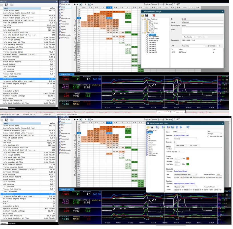
For example I think here is my simple math for wideband input using the EGR
[2811.10]/.5+9.5
I would adjust the +9.5 until the gauge matches the in-car logging wideband data.
It won't be perfect and may offset depending on electrical load. So at night I have +9.4 and during the day +9.6 or 9.7 for example, depending on the a/c, headlights, and so forth.
I have a new computer and all of my tuning stuff is on an old hard drive, and some of the imported maths are missing and some are wrong, I don't know why but between the old and new computer I lost a bunch of things so this is taking me a minute to find what I'm trying to show.
I got the channels setup finally (that took 10 minutes!) And imported an old log and the maths are shown here using the EGR sensor. I am not sure you are using EGR or A/C or canbus or what. But if you are using EGR sensor this is the math and kind of graph you want to produce which can help you tune the engine.
wideband-math-and-output-graph.jpg
Im using the serial port to log the wideband, i saw some videos on how to do the math and charts and they look pretty different, are tuning in afr or lamba. Also where do i change the voltage output? Im sorry I'm causing you a lot of trouble, I'm 17 and I'm just starting to learn.
Serial port? 9 pin cable?
This?
https://forum.hptuners.com/showthrea...l-port-adapter
What computer do you that still has a serial port? Are you going from serial to USB?
I've never done this way and I am not sure if it is a preferred method or outdated. Does the wideband itself have a serial cable? Or did you splice some wideband wires into a serial cable?
Can you post the type of wideband part number? So I know what gauge or sensor you have
i got the aem 30-0300 i= did use the serial port 9 pin to usb. i only had the male serial data-usb cable so i solder the blue wire from the wideband to the pin 2 and black to 5
I looked at your log file again. Last time I Looked it was different, I saw two O2 sensors working, I don't know why. But my scanners been doing weird stuff all day.
This time I can see B1S1 looks like you disconnected that sensor. B2S1 is working and showing lean which matches the wideband lambda. If you right click in the scanner you can change from lambda to A/F ratio gasoline, which I recommend.
It looks like it could be working, just verify by comparing gauge reading with data-log values. Make sure they match, thats all. Once you are sure they match you can actually tune the engine. Right now looking lean, Disable closed loop and STFT LTFT all of that. I also prefer to disable the maf sensor and tune the VE map using MAP sensor only. There are a few diagnostics to take care of before you really start tuning though. Do any cleaning, make sure a couple plugs look good enough to tune on. Perform a compression test if you need. I would pressure test the intake system to find leaking and even clean it if its kind of old. Make sure the PCV system is intact and hooked up properly. Use a new PCV valve if the one is old. These basic mechanical approach are important before you spend hours tuning an engine with some mechanical issue which can ruin all of your hard work. Look up how to disable the maf sensor properly also, I forget how exactly its like disable the SES and set them to MIL on first error I think.
If you can provide a picture of a couple spark plugs coloration, the engine, vacuum hoses, fuel regulator, these pictures will help everyone to help you.
The year, displacement, engine configuration of all the parts,
Post your HPT tune file so people can look inside and help you with changes.
Consider making a new thread with these details once you sorted out the wideband stuff. Tune file, a couple logs, pictures.
b2s1 is the passenger side where i have my regular o2 senor and on the driver side i have my wideband witch shows its disconnected i Guese because i don't have another regular sensor. i changed to a/f ratio gasoline, is this going to log afr insted of lamba? tomorrow Ima try to do the diagnostics and calibrate the tune to disable the closed loop and all that. and final question for today so if it is reading correctly and it matches the gauge what is the cause for the high numbers in the chart?
You can log however you want to log. Its preference. I prefer AFR gasoline because it gives more resolution than lambda. 11.8 vs 11.2 afr is a big difference in some situations, but hard to see in lambda at a glance for specific frames of operation.
If the gauge reads 16.5:1 and the log reads 16.5:1 they are the same thats good. That means the log is reading the sensor the same way as the gauge. This is the first sanity check.
The next sanity check is to adjust the a/f ratio manually using the scanner. Adjust the a/f ratio up and down and see how the gauge / log is affected. Rich a/f ratios should correspond to rich a/f ratios on both, the linearity and continuity between them as well as whether they can actually detect a wide range of a/f ratio values. In other words if the sensor says 16:1 and the log say 16:1, what is the real a/f ratio? Sensors and computers are 'dumb' they don't actually know anything. So you need to adjust the actual a/f ratio up and down manually and watch the behavior of the wideband to see whether it follows along with your changes, to see if its working. For example if there is a large exhaust leak the sensor will still say 16:1 even if you keep enriching the a/f ratio very rich. This is sanity check number 2
Once you get those done and the basic mechanical maintenance aspects concluded you can focus on configuring the file. I recommend you go through every single window and table and make sense of them. Always start with displacement and injector size and injector data and all of that FUEL table stuff and switch the software into 'advanced' mode so you can see everything they have to offer. Look at the Operating system and determine whether it's options and available tables will fully suit your needs. All of this before any tuning is done.
The 'high numbers' if they are accurate reflect air fuel ratio. It means the engine is running lean. It needs to be tuned or something is wrong mechanically/diagnostically. For example fuel pressure could be low or the injector size is wrong or there is a clogged fuel filter or something like that. This is why we rule out the diagnoatics and maintenance aspects first, like compression test, change the fuel filters, check the fuel pressure, check the plugs. A misfire could cause a high air fuel ratio reading like 16:1 if there is a plug not firing because its already been fouled or simple not connected. The wiring is also a suspect, once the engine runs decently and the plugs are keeping clean you should use the scanner to disable 1 injector at a time to see if they correspond to the correct cylinders, by unplugging the same injector for example.
5.3/4l80e/turbo playthrough
https://www.corvetteforum.com/forums...ge-budget.html
cancer research
https://www.mdpi.com/2306-5354/10/1/96
so i was checking for exhausts leaks and i found one at the end of the exhaust by the tip could affect it? and also in the header to the heads theirs a very small leak. i tested it with soapy water and a vacuum could that be affecting it too?
The way fluids move (air is a fluid, exhaust is a fluid) is hard to describe even with mathematics. Yes of course it may affect it. But it could also just as easily not affect anything. The fluids could be leaking out but not in, or they can be siphoning oxygen into the system from the air, it depends on the exhaust pulse, fluid momentum, turbulence, distance between pulses, all kinds of variables.
In my case when I look at a wideband reading I can generally tell if there is some issue just by watching the behavior and making changes to the engine. However you may not have that experience to be able tell just by looking.
So what I recommend in your case is to fix the leaking. Any leaks BEFORE the sensor will generally have some influence. Any leaks NEAR the sensor in front or behind, within lets say 1 foot or so, will also generally influence the sensor.
Any leaks more than 1 foot away DOWNSTREAM from the sensor, if they are small, should not influence the sensor much or at all. But again fluids are tricky. A leak After the sensor could influence the sensor by dragging in oxygen and creating an eddy/swirling fluids near the leak which make their way back towards the sensor. It depends also strongly on exhaust temperature. A very hot exhaust is flowing rapidly , high velocity and expanded, it may leak a 'spray' pattern. Whereas in places where exhaust has been cooled down, the gas is condensing, reducing in volume, it can create a suction which brings in oxygen from the outside air and interacts with the oxygen sensor.
You can probably test the sensor using the scanner on the running engine by adjusting the a/f ratio up and down and see if it 'makes sense'. It might not be so hard for you to tell if you can give it enough time to understand what you are looking at. Or , take a video, and i can help you.
how do i adjust the air-fuel ratio up and down so i can try it tomorrow and sent you a video, also i think i fix the leak in the headers a bolt was loose and i just tightened it
Last edited by Jacog; 08-24-2023 at 09:30 PM.
If the engine is running and you've completed the mechanical issues (or just want to try anyways) You can use the scanner to take control over the air fuel ratio and dial it up and down.
Before you do that I would recommend setting up at least the tune file's displacement, injector size, injector data. The closer you get the injector information in the computer the more diagnostically useful the scanner will become when you take control.
I guess you have a gauge. You will watch the gauge and adjust the air fuel ratio, video the gauge behavior. Basically you need to see a steady number, no flinching, jumping around. If the plugs are fouled or there is some leaking the number will be jumpy or not even make sense. There are also low quality and high quality units, AEM is a good high quality unit and will be more easy to work with I think you have the AEM.
Adjust the a/f ratio low and high, the gauge showing 15's 16's the engine starts to run lean and pop misfire gauge gets jumpy, good. The number gets low 13's 12's the engine smooths out smells rich, good. You let it rest at 14.5 to 15.0 and the engine is smooth (depending on cam) smells good, steady number, good.

 Reply With Quote