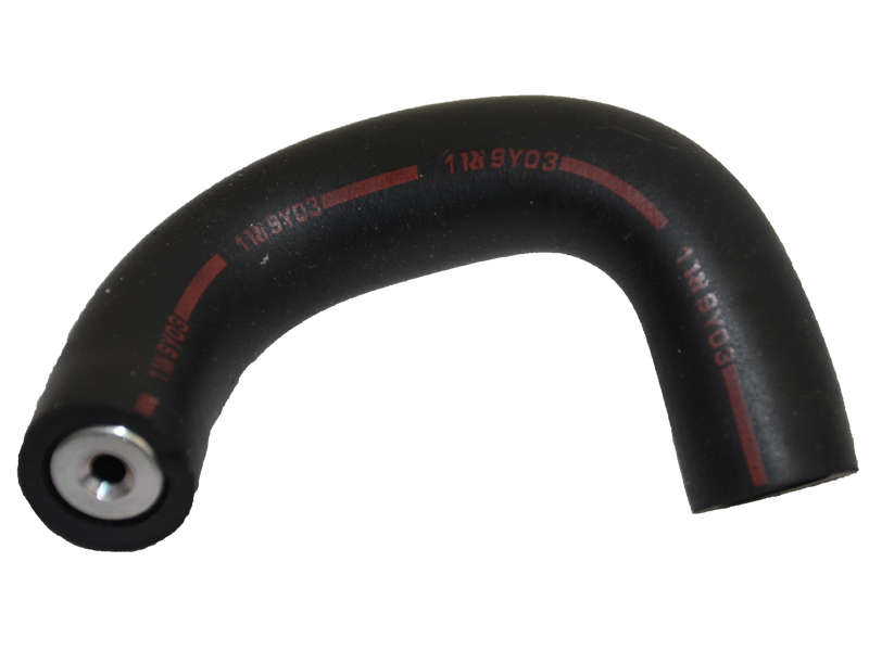
Well yes. It's being called a venturi because of where it's being located and oriented. It does indeed pull vacuum "venturi effect" because of where it's located with high speed air moving around it to act as a vacuum on the oriented port. BUT you are somewhat correct. The area where it is being installed isn't reduced in size any to increase the velocity on it as the air should already be moving fast enough where it's being installed. Granted turbo or centri being used. It is just a simple angled barb turned and cut specifically to achieve what they're after. It may or may not have an orifice in it to aid in this. I really don't know.
https://www.eliteengineeringusa.com/...-venturi-barb/
To the first post above. That is talking about a dry sump system in regards to it's pcv system already technically having a way to drain back into the oil sump and removing said oil via an incorrectly installed catch can system in this case will indeed remove the oil from the system and if removed enough times it will lower the oil level. I thought checking oil level was par for course when emptying catch cans? Guess not for some owners if GM released this.
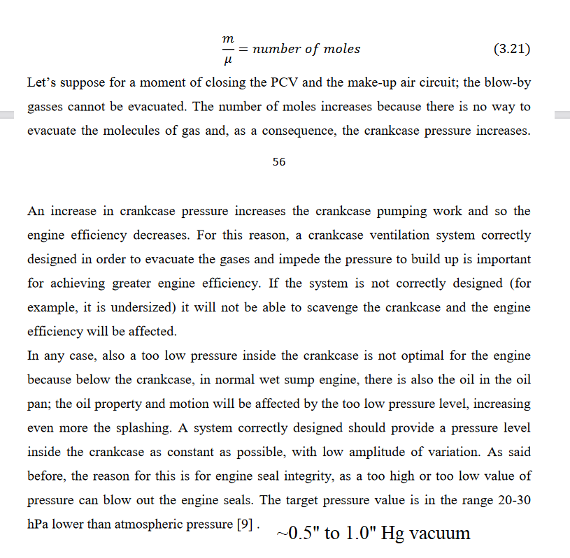
As for vacuum on the crankcase at wot. I know vacuum adds hp. Nascar engines run a single chamber of their oil pumps just to pull vacuum on the crankcase's. It's good for about 70hp on those engines if memory serves. It's been 2 decades since I got to mess with any so I don't remember vacuum levels or anything like that. How much vacuum with wot is safe and how much do you need to make extra power and keep the rings from fluttering?


Originally Posted by 92rsz


 Reply With Quote