Page 3 of 3 FirstFirst 123
Results 41 to 56 of 56

Thread: Lower VE with newer/better engine?

  1. #41
    Tuner
    Join Date
    Aug 2015
    Location
    Okemos, MI
    Posts
    115
    Quote Originally Posted by kingtal0n View Post
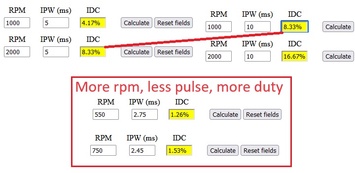
    Right, we do pulse for torque and VE. And we do duty cycle for energy content per unit time.
    And we use duty cycle when verifying that the injectors can keep up with fuel demand.

    Quote Originally Posted by kingtal0n View Post
    Energy from fuel may be turned into heat and lost (melting parts).
    Sometimes, the heat energy isn't lost, but recaptured and put to work. Catalytic converters capture the heat in order to enable their conversion reactions. Heater cores allow us to stay comfortable when it's cold out. And turbochargers recapture some of that heat energy and turn it back into kinetic energy.

    Quote Originally Posted by kingtal0n View Post
    and there is a restorative feature with respect to conservation of energy which comes into play further into this discussion.
    I'm curious what you're referring to here? Exhaust pulse scavenging?

  2. #42
    Advanced Tuner
    Join Date
    Apr 2022
    Posts
    217
    Quote Originally Posted by JakeRobb View Post
    I don't get a lot of time to work on it, especially during the week. Was really busy during the holiday weekend, too. That said, I confirmed the need for a TPS relearn last night (min % was 0.4%). Did that, and I am now seeing TPS 0.0% when not on the throttle, so I think it'll idle now. I also identified a throttle cable issue, wherein I can't open the throttle all the way via the pedal (it stops at about 50% with the pedal on the floor). That was all the time I had, and I haven't started it yet to test.
    !
    IS the blade only opening halfway or the tps percentage only gets to 50% i had that issue when i was logging two tps pids where one was canceling the other out it would go 100-50 100-50 on and on while pedal was to floor

  3. #43
    Senior Tuner kingtal0n's Avatar
    Join Date
    Feb 2017
    Location
    miami
    Posts
    1,799
    Quote Originally Posted by JakeRobb View Post
    Okay, I've had time now to digest.


    Yep, we've covered that.

    Although I'll quibble with your choice of words -- "bigger" and "larger" to describe more aggressive cams. The only real thing you could be referring to is valve lift, as higher lift literally translates to the camshaft being physically larger. But you can actually make an engine more efficient by employing lobes with more lift, and/or more aggressive ramp rates, so long as the timing of the open/close events remain unchanged.
    Its hard to specify one or many camshaft details that influence whether negatively or positively the conservation of energy of the rotating combustion engine, which is what this is all really about. The word "bigger" simply implies we are losing some energy, somewhere, because the camshaft went away from OEM design. It could have gotten reduced lift and reduced duration but the ramps could change. Or the cam could be retarded or advanced "bigger" same camshaft profile. I am merely setting up a global assumption that when 'things get worse' its because the camshaft got 'bigger'. However I appreciate your desire to be specific and this is something I will carry forward into this discussion as these exchange of energy within an engine evolve on paper assumptions for pseudo analytical solutions, conceptually at least.


    The thing is that it's pretty uncommon for people to replace OEM cams with aftermarket ones that have identical-to-OEM timing characteristics and simply use a different lobe profile. Aftermarket cams also vary the lobe separation and the exact timing of the various open/close events, and it's these changes which lead to pumping losses at low RPM.
    We must keep in mind many engines provide alternative lift strategy (v-tec) and many have real time camshaft separation (Separate cam for intake&exhaust plus realtime advance/retard). When the OEM from some manufacturer decide how they should be programmed I generally make the assumption it was for maximum conservation of energy which means highest economy and perhaps best emissions. How that happens and the result of which is the topic of this discussion because we need to look at fuel as an energy source and the places energy winds up.


    The reasons OEMs don't do this are primarily related to cost and parts longevity. Those larger lobes would demand a better (more expensive) spring in order to meet durability targets, and that might not be the only part of the valvetrain which might be compromised. Although as CAFE targets become more and more aggressive, I suspect the balance is changing here, with OEMs willing to employ more expensive valvetrain components in order to achieve higher efficiency. Of course, most of the vehicles in any given manufacturer's lineup use VVTL (and usually DOHC) to greatly increase the RPM range during which they can operate efficiently while still meeting performance targets.

    So yeah, let's maybe say "higher performance" or "more aggressive" or "hotter" (figurative, of course) instead of "larger"?
    I will be entirely specific in the following examples exactly how when and where why the energy will go


    Increase in SD is not something I had considered. What is it about a more aggressive camshaft that causes this? It's not like the lobe profiles vary from one cylinder to the next....
    I imagine that this is a super-complex scenario where things like reflected exhaust pulses are coming into play at some RPMs, and having a greater effect on airmass due to increased overlap. And probably a handful of other similarly complex dynamic interactions, all contributing to the situation together.
    The Reason is flow work (momentum of fluids) and water hammer. These are places where energy is stored and either supplement or deprive cylinders from air mass. The first cylinder to fire for example may have some reversion and low VE. The next cylinder gains additional VE because the fluid momentum in the runner thanks to the reversion up the intake runner of the previous cylinder. Finally the third cylinder can receive the benefit of water hammer (sound arriving to the intake valve) from the first cylinder. The fourth cylinder is now deprived because of the bunching up of fluids near the intake valve of the second cylinder causes a stall in the intake plenum which reduced all of the momentum so when the intake valve opens it needs to build momentum waiting for the piston to descend. And then of course the exhaust will play a role during overlap, can it evacuate the cylinder or will it contaminate the cylinder, you seem to have though about the exhaust a bit so I won't get a bunch of exhaust examples. But you should clearly see that depending on the runner length/volume and plenum volume and interactions between cylinders how specific rpm or operating conditions can influence cylinder fill even at WOT. for example 2jzgte engines are notoriously lean in cylinder #6 at high boost because of certain plenum designs.

    It makes sense that increased SD would be the cause of the characteristic lope, although it doesn't quite sit right with me that the variance could be so great as to cause the significant lope we've all seen with the most aggressive cam specs.
    For this lets Notice that direct injected vehicles may lope like a carb engine. Notice that long duration cams cause fuel to spray back out of carbs at idle (familiar with reversion). Then keep in mind every combustion event results with a rapid speeding up and then slowing down of the engine rate, (rate is positive, then negative or approaching zero until the next event, depending on the number of cylinders), we can connect these ideas and begin to form assumptions thereby eliminating variables. First, direct injection maintains all injected fuel inside the cylinder, despite reversion during piston ascent on compression stroke while the intake valve is open. Whereas a port injected engine which injects fuel post overlap and post EVC can still reverse fuel and air into the runner. And both still maintain lope character, thereby eliminating lost fuel as the culprit more or less. Which leaves only dynamic compression (VE changes over time or SD). Some lope character is rhythmic and some is sounding more random. A rhythm establishes that some specific cylinders are repeatedly creating intake system momentum and water hammer features that result with unbroken cadence.

    My 5.3 has particular rhythm


    It is specific cylinders which repeatedly have the low/high VE due to the intake design and practical function of the OEM exhaust manifold which I imagine would obliterate most acoustic tuning but not necessarily momentum flow (overlap scavenging) attributes therefore I believe if I swap to a different style intake manifold with shorter runners it may lope differently unless the scavenging of the exhaust was significant in some way to the rhythm. Nevertheless its a good example of the cadence due to deviation between cylinders.


    I'm assuming we're still referring primarily to low RPM? If these things were problematic at all RPMs, then we wouldn't see more power anywhere in the rev range.
    This is where we must discuss energy. Where did energy go and whether it can be stored or is simply lost. Momentum in fluids and water hammer has potential to be useful or wasted. When it is wasted we must make up for it with pumping loss. When it is useful we still don't gain energy because energy cannot be created and everything to turn the engine comes from fuel so it is a matter of efficiency, or brake specific fuel consumption.
    Lets compare idle rpm to wot high rpm for stock cam and long duration cam situations.

    First, IDLE
    For the stock camshaft in typical modern vehicles we have cylinders which routinely sip air and get their intake valves closed before reversion much occurs which prevents backing up or stalling of momentum flow within the runner and plenum. Energy is more easily conserved. We also have a proper diameter stock exhaust system which maintains high exhaust gas velocity which assists the cylinder fill (Scavenging) as evinced by the massive loss of torque which occurs when one chops off the exhaust system of the stock engine. The OEM engineers often take advantage of the exhaust scavenging and go to great lengths to provide that energy for cylinder fill because it means reduced pumping loss which means superior economy, they turn exhaust energy into cylinder fill and save fuel. The stock cam also has minimal overlap which can keep more fuel from leaving the cylinder to the exhaust system.
    The ideal behind the factory camshaft is to put good cylinder fill near low speed driving situations and efficiently turn fuel to energy by conserving fuel in the cylinder, increasing (dynamic) compression and reducing pumping loss.

    When we write a VE Number into the VE table the ecu translates that into a pulse for the injector based on manifold pressure and temperature. Lets assume temp is constant from here out so we can focus on manifold pressure only.
    Whether the engine is at 800rpm or 7000rpm the VE number in the VE table translates into the same pulse number for a given manifold pressure assuming all modifier (for any ECU) tables are eliminated.
    Lets make some rough example guesses that follow these logic. Or we can use my original VE table or an OEM VE table, same sort of thing.
    The VE at low rpm idle at around 550rpm could be lets say 40%. Because the cam is stock and has good efficiency to bring in airflow and conserve fuel and energy this 40% represents the necessary pulse width supply energy to the cylinder to keep the engine rpm constant (idle speed). It does not necessarily mean the cylinder is 40% full, the VE table is a fuel table after all. This fuel pulse is also reflected in the engines BSFC and dynamic compression, the tighter we can squeeze the fuel and air together the more energy efficiency results. This 40% fuel pulse is important to realize that is not accelerating the engine but rather just making up for the friction and maintaining its rotating angular velocity.

    Now, lets swap to the aftermarket long duration camshaft. Then engine still has the same friction and for the sake of this example lets assume will idle at the same RPM. If we could turn the same amount of fuel into the same amount of energy as before we could still idle the engine exactly the same, since we didn't change lift or springs or basically friction. A tiny bit of extra energy to hold the valves open longer is negligible. So why does the long duration camshaft require more fuel to idle in practice? Because the valve is open longer the reversion during compression stroke is creating a counter momentum flow in the runner/plenum which challenges incoming air pressure gradient or velocity component. Energy is being lost because the valve events are interfering with smooth energy transfer from intake to cylinder. Energy must come from fuel, therefore more fuel will be required to make up for these losses. Furthermore the increased overlap gives fuel an opportunity to escape depending on the spray timing. It also allows more cylinder air mass to escape into the exhaust system which is also a component of lost energy since energy was used up to bring that air mass in to begin with, more fuel wasted. Finally we encounter the concept of load and vacuum to tie this example together. Because energy is being wasted more fuel is required and needs to be burnt, so more air mass is also required. Yet our cylinder is losing air to the intake and exhaust which means it is losing air volume. The only way to make up for this lost air volume is with density, or pressure (manifold pressure). This means more manifold pressure will be required to increase the air density (increased load or throttle position or iacv opening), since energy is being lost and we want to burn more fuel. The brake specific fuel consumption is worse because of the energy losses and the fuel injector pulse must be increased to make up for the lost energy. The ECU may inject the fuel directly via the new MAP load values but it won't know about the lost energy and reduced BSFC so generally this means we need to increase the VE value manually even though the VE in terms of volume could be much less than it was stock. So, more fuel used, VE is worse, bigger VE table values to make up for lost energy if needed.

    Now the WOT example, much easier
    At 'higher' RPM the valve events of a stock camshaft generally prevent momentum flow from providing cylinder fill during piston ascent on the compression stroke.
    With the long duration camshaft the momentum flow or flow work of incoming air is able to continue filling a cylinder while the piston is ascending.
    Combined with the proper scavenging 'LSA' and 'overlap' We can evacuate a cylinder effectively and fill it effectively with the long duration camshaft at high rpm. Whereas it chokes with the stock cam gradually losing fill opportunity.
    In terms of VE this means the VE will be less for the stock cam and higher for the long duration cam, but these values literally reflect the VE or dynamic compression of increasing air mass with the same density at high RPM, assuming same temperature. Notice momentum flow can increase air density resulting with cylinder fill beyond 100% in theoretical VE terms... we must remember the literal VE can only be 100% but the theoretical VE may be affected by air density apart from temperature, in other words momentum flow or flow work can increase air density at the same temperature. Likewise harmonic or water hammer effects can do the same thing, a pressure wave of higher density may overfill a cylinder at some constant temp T. These influences, momentum, sound, valve timing, work together to improve cylinder fill when timed applicably.


    I have to argue with you here. As previously noted, the VE table has RPM as one of its axes. So when any one number goes up or down, it is doing so in the context of a specific RPM, and therefore an increasing number does correspond to an increase in both pulse and duty cycle at that RPM.
    I don't know what you are saying. Its okay if you want to use math here. I will show you exactly what I am saying


    Um, duh? Not sure why this is a point you feel you need to make at all. Of course it's a fuel table.
    People say I should be banned for saying the VE table is a fuel table. I was just making sure it really was an I am not crazy. Thanks for that. I Know its really because the internet is a popularity contest and whether you are right or wrong doesn't matter, they just don't like you or not.

  4. #44
    Senior Tuner kingtal0n's Avatar
    Join Date
    Feb 2017
    Location
    miami
    Posts
    1,799
    Quote Originally Posted by JakeRobb View Post
    And we use duty cycle when verifying that the injectors can keep up with fuel demand.
    Yes and no. Yes because of course you are right. But no because we blatantly assume brake specific fuel consumption is a specific number and this is simply not the case. There are so many factors it derails this discussion. However the way I do it now that I've setup hundreds of performance vehicles over 25 years is simple. I shoot for around 40-50% injector duty maximums. There are a few reasons why I settled on this strategy.
    1. Injector drivers stay cooler and more consistent for high output situations
    2. Often, 'customers' are changing around fuel density and air density as an afterthought
    3. Fuel injector quality is far superior than it was in the old days (90's) where larger injectors meant terrible idle quality, we can be very precise now
    4. Some engines respond well (midrange torque and response) to spraying during intake stroke between 320* before top dead center compression and say 210* btdcc (haltech reference periods) which means you need to get all fuel in within a relatively short window at mid-range torque situations.


    Sometimes, the heat energy isn't lost, but recaptured and put to work. Catalytic converters capture the heat in order to enable their conversion reactions. Heater cores allow us to stay comfortable when it's cold out. And turbochargers recapture some of that heat energy and turn it back into kinetic energy.
    Well no, none of those put work back into the engine and restore or improve fuel economy. Not really 'work'. I know what you mean but when I say work I mean doing work to counteract the friction of rotating which keeps the engine moving. Turbochargers unfortunately do not improve fuel economy, believe me I've tried and mathed it out a hundred ways it just doesn't happen, there is no turbo 'work' helping the engine run more efficiently, always worst bsfc. Sigh.

  5. #45
    Senior Tuner kingtal0n's Avatar
    Join Date
    Feb 2017
    Location
    miami
    Posts
    1,799
    Quote Originally Posted by edcmat-l1 View Post
    I would completely ignore that guy. Few weeks ago he didn't even understand the definition of VE.

    Lets see

    From 2013
    https://www.sr20-forum.com/tuning/!2...75#post!922675
    This is due to a dropping volumetric efficiency. Extra timing is safe when the VE (torque) is falling off.

    From 2003
    https://www.thirdgen.org/forums/powe...ml#post1270941
    Yes, peak torque and VE do happen at the same point, but that is because the torque curve and VE curve are the same curve. If your engine ran at 100% VE all the time your torque curve would be a flat line with the same value (ex, roughly 399lb-ft for a 350).

    Bored. Boring. You bore me
    weak attacks. name calling. just really lrn2insult somebody properly

  6. #46
    Senior Tuner kingtal0n's Avatar
    Join Date
    Feb 2017
    Location
    miami
    Posts
    1,799
    Oo heres a good one where I exposed some liars. In sr20det land there is a head called the VE head which everyone assumed means it can increase the VE. When I know for a fact the stock sr20det head can do 100% VE as it sits and this is evident in the torque curves. We go around and around but as usual I show data and numbers and do math and everybody else just has words... always with the words...
    https://zilvia.net/f/showpost.php?p=...1&postcount=31
    Pretty easy to see torque scale with boost. Just focus on torque because that is cylinder fill, which can only be 100% max. The engine clearly makes a max VE approaching 5500rpm where boost stops rising, max VE = max cylinder fill.

    So yeah. Pretty hard to write a tuning software application without knowing what VE is.

    https://www.thirdgen.org/forums/dfi-...der-950-a.html


    Just defending as usual. But really, really well.

  7. #47
    Senior Tuner
    Join Date
    Mar 2022
    Location
    Indiana
    Posts
    2,945
    Quote Originally Posted by JakeRobb View Post
    That's what I wanted to know!

    I am not asking for specific help with my tune; I've scarcely begun tuning. The very first changes I was making didn't make sense to me, so I didn't save them. Instead I came here and posted this thread to find out what was up.

    Turns out my intuition was flawed; I didn't realize that a bigger cam would be less efficient at low RPM. That bit of my intuition is corrected, but only partially; what is "low RPM"? I am sure it varies by engine and cam, which is why I shared those details when asking if anyone here had an intuitive sense of the RPM range where I should start to see VE advantages over the stock LS1. If they could share that, even if it's just a guess based on experience, then I would could take that and have it in mind when proceeding with my tune changes, and could feel a little more confident moving forward.

    Turns out I also have some other issues I need to iron out before I go back to VE tuning.
    Well if you need any help feel free to post here or even PM me directly. Any questions about histograms, procedure, or general settings I'll be glad to help. Good luck with your build and tuning. Cammed LS3 in an M6 Fbody is going to turn some heads.

  8. #48
    Tuner
    Join Date
    Aug 2015
    Location
    Okemos, MI
    Posts
    115
    Quote Originally Posted by Lxjoshxl View Post
    IS the blade only opening halfway or the tps percentage only gets to 50% i had that issue when i was logging two tps pids where one was canceling the other out it would go 100-50 100-50 on and on while pedal was to floor
    I set my phone in front of the TB with the airbox lid and MAF removed, started recording video, then hopped in the driver seat and pressed the throttle to the floor a few times, making absolutely sure there was no interference from carpet / floor mat / etc. The video confirms that the throttle blade only opens about halfway.

    On a separate occasion, I was doing the same thing with the pedal and watching TPS voltage. I saw a peak voltage of 2.25. I didn't look at TPS % at the time, and it was before I did the relearn anyway.

    I'm pretty confident it's just an issue with the cable.

    Part of me wants to just switch to DBW. It?d be cool regardless (and fitting with the numerous other clearly-overkill modernizations and upgrades I've done). Plus, I suspect it would be a net weight savings, since I would be removing the cruise control module and the cruise actuator, and weight savings are always nice! This is primarily a street car, and I am a heavy cruise user, though ? so I'll only go that route once I'm sure that I can retain cruise control functionality.

    Quote Originally Posted by SiriusC1024 View Post
    Well if you need any help feel free to post here or even PM me directly. Any questions about histograms, procedure, or general settings I'll be glad to help. Good luck with your build and tuning. Cammed LS3 in an M6 Fbody is going to turn some heads.
    Thanks!

    I was poking around today in Scanner, learning how to set up graphs (which should really be called tables) and histograms. I can feel some questions forming, but I need to do this more while connected to a running engine (or at least with datalogs containing more than 20-30 seconds of runtime) before I even know what it is I want to ask!

    Earlier you talked about copying from the LTFT histo and then using Paste Special on the VE table to apply progressive adjustments. From what I have seen so far, I think I actually need to copy from the LTFT graph (again, actually a table). A histogram is a bar graph, and Scanner's histogram function doesn't seem to support rendering more than two axes, but you need to copy data from a source with three axes in order to apply it to the VE table in the way you described.

  9. #49
    Senior Tuner
    Join Date
    Mar 2022
    Location
    Indiana
    Posts
    2,945
    Easy, poindexter Scanner in fact calls them graphs, but they are histograms. Counts, frequency of data, are included, and the data set is continuous. Really, the terminology is irrelevant to the results.

    VE should be pre-defined by default with LTFT and STFT in scanner. I like to include LTFT+STFT as well.

    Keep in mind that in SD, unless upgrading to Speed Density Enhanced, that the secondary VE table and low spark tables are referenced by default. So, make Secondary and Primary match by selecting all>copy with axis.

  10. #50
    Tuner
    Join Date
    Aug 2015
    Location
    Okemos, MI
    Posts
    115
    Quote Originally Posted by SiriusC1024 View Post
    Easy, poindexter Scanner in fact calls them graphs, but they are histograms. Counts, frequency of data, are included, and the data set is continuous. Really, the terminology is irrelevant to the results.
    Screenshot from Scanner's help docs on the HPTuners website:
    Scanner.jpg

    They get this correct: there are tables (2d grids of numbers) and histograms (data visualized using rectangles). The confusing bit is that the entire thing is under a feature called Graphs. Histograms are a kind of graph, but tables are not.

    But my point was not that the terminology was wrong, but rather that I was asking which one you meant, because if there's a way to view a histogram of LTFT with axes for RPM and MAP, I haven't found it. I've only found this in table form. I know I can create my own histograms, but they seem to be limited to 2D, and 3D would be required to render a histogram of LTFT against both RPM and MAP. A 3D histogram would look like this:
    sphx_glr_hist3d_001.png

    Related question: does Scanner have the ability to render 3D surface plots like you can do in Editor? I think it would sometimes be helpful to view things like LTFT in this way. (This sort of visualization would be equivalent to a 3D histogram.)
    vcm_editor_table_3d.jpg


    Quote Originally Posted by SiriusC1024 View Post
    VE should be pre-defined by default with LTFT and STFT in scanner. I like to include LTFT+STFT as well.
    Yep, predefined as tables.

    When you say LTFT+STFT, do you mean you are summing the values for each RPM+MAP, and then filling a table with the result? I guess that makes sense, especially if you're trying to tune in real time. What causes STFT to clear? What causes short term trims to get promoted to long term?

    Quote Originally Posted by SiriusC1024 View Post
    Keep in mind that in SD, unless upgrading to Speed Density Enhanced, that the secondary VE table and low spark tables are referenced by default. So, make Secondary and Primary match by selecting all>copy with axis.
    Good note, thanks!
    Last edited by JakeRobb; 11-28-2023 at 09:31 AM.

  11. #51
    Senior Tuner
    Join Date
    Mar 2022
    Location
    Indiana
    Posts
    2,945
    Here is how you'd do it for VE. STFT and LTFT are already there ready for you. All you have to do is edit the axes. Here's what I mean by LTFT+STFT. It's just like those other two, but the parameter logged is what changes.
    stft+ltft.png

    Square is a rectangle, but rectangle is not a square.

  12. #52
    Tuner
    Join Date
    Aug 2015
    Location
    Okemos, MI
    Posts
    115
    Quote Originally Posted by SiriusC1024 View Post
    Here is how you'd do it for VE. STFT and LTFT are already there ready for you. All you have to do is edit the axes. Here's what I mean by LTFT+STFT. It's just like those other two, but the parameter logged is what changes.
    Got it, thanks. (BTW, that's a table config, not a histogram.)

  13. #53
    Senior Tuner
    Join Date
    Mar 2022
    Location
    Indiana
    Posts
    2,945
    Yes, it's a rectangle.

  14. #54
    Senior Tuner
    Join Date
    Nov 2006
    Posts
    2,742
    Quote Originally Posted by JakeRobb View Post
    Got it, thanks. (BTW, that's a table config, not a histogram.)

    The scanner used to call them histograms.. then a few versions back they changed the name to graphs and added histogram
    Tuner at PCMofnc.com
    Email tuning!!!, Mail order, Dyno tuning, Performance Parts, Electric Fan Kits, 4l80e swap harnesses, 6l80 -> 4l80e conversion harnesses, Installs

  15. #55
    Tuner
    Join Date
    Aug 2015
    Location
    Okemos, MI
    Posts
    115
    With many thanks to all of you, and no thanks to my busy schedule, I'm pleased to say that I've finally gotten the tune ball rolling. We have 8" of snow on the ground and I have no dyno, so I've only managed to tune the cells I can reach from idle and with some quick throttle blips so far, but I'm prepped and ready to datalog some street drives and make more adjustments as soon as the roads are clear. Still need to get my wideband wired in so I can do high-RPM stuff too (I'm going to wire it to the EGR circuit so I can have it as a permanent input without any clutter).

    Quote Originally Posted by ns158sl View Post
    Quote Originally Posted by JakeRobb View Post
    Quote Originally Posted by SiriusC1024 View Post
    All those settings other than High RPM disable will be used to tune either MAF or VE.
    If VE isn't right when you do MAF, wouldn't that lead to a tune where the MAF calibration was wrong, and the VE was also wrong in an equivalent/opposite direction? And wouldn't that lead to an incorrect tune in situations where the MAF isn't being used, since the MAF cal wouldn't be compensating for the incorrect VE?
    Kind of. You are thinking if you are in hybrid mode. Hence with Gen3's it seems easier to do it the old fashion way of disable MAF, dial in your VE, Then disable dyn air and tune the maf.
    Bringing this one back around for some closure: I think I get it now. I didn't realize that there was a MAF-only mode, where it's using the VE table approximately not at all (I'm under the impression that it's still used for some transient calculations?). I thought there was pure VE (speed density) and what I now know is called hybrid. What's the best resource to educate myself on the modes?

    At a minimum, I'm hoping to learn:
    1. Are there more than these three modes (MAF only, VE only, hybrid)? If yes, what are they? (I'm talking primary operating modes, not things like DFCO or PE which, as I understand them, modify the output of what I'm calling the primary mode rather than coming up with their own output from some other table(s).)
    2. When is each mode active in a normal factory tune, and under what circumstances might I want to adjust the thresholds / criteria? (I understand the choice to forego them all and run pure SD; looking to learn beyond that.)
    3. How does hybrid mode behave?
    2002 Z28 M6 TUNE IN PROGRESS, targeting ~500whp -- 24x heads+cam LS3 controlled by the factory 0411. Street + HPDE car.
    1987 Grand National ~450whp, 58mm turbo, controlled by Fast XFI 2.0. Cruise + show car.

  16. #56