Results 1 to 15 of 15

Thread: MPVI permanent install

  1. #1
    Tuner in Training
    Join Date
    May 2004
    Location
    Posts
    46

    MPVI permanent install

    My problem is that the MPVI will drain the battery if I leave it hooked up with the green light on. If I disconnect it to leave the car in the garage for a week then sods law says I touch the serial against the MPVI and the resulting spark blows the fuse in the passenger footwell.

    What would be nice is an on/off switch on the MPVI so that I can just turn it off rather than having to disconnect it (with the risk of shorting).

  2. #2
    Senior Tuner
    Join Date
    May 2003
    Location
    Santa Clarita, Ca
    Posts
    962
    Run the power wire of the OBDII port to a switched igntion source instead of battery...


    There should be no sparks when you connect the USB cable. If there is, something is wrong with your install or laptop (a bad inverter?). Fix that before you ruin the MPVI, as that is not covered under warranty.

    -Ken
    Last edited by Casey; 02-25-2008 at 10:36 AM.

  3. #3
    Tuner in Training
    Join Date
    Feb 2008
    Posts
    31
    Quote Originally Posted by Ken@HPTuners
    Run the power wire of the OBDII port to a switched igntion source instead of battery...


    There should be no sparks when you connect the USB cable. If there is, something is wrong with your install or laptop (a bad inverter?). Fix that before you ruin the MPVI, as that is not covered under warranty.

    -Ken

    FYI,
    I blew a fuse a week ago after reconnecting the serial cable to the MPVI while the other end was connected to the OBDII port.

  4. #4
    Tuner in Training
    Join Date
    May 2004
    Location
    Posts
    46
    Thanks Ken, good idea - that's pin 16 - right?

    How do I access that, just cut into the cable?

    The spark/shorting issue is not when I connect the ODBII serial to the MPVI pro, it's when the ends touch but are not lined up - for instance if the screw in the serial connector (other end of the cable from the OBDII port) touch the metal surround of the serial connector of the MPVI, then it sparks. If I line them up for connection then no problem, no spark. The problem is that I leave these unconnected in the centre console and they can easily touch accidentially.

  5. #5
    Senior Tuner
    Join Date
    May 2003
    Location
    Santa Clarita, Ca
    Posts
    962
    Yes its pin 16. Just cut the wire on that goes to the OBDII connector and route it to some fused ignition source.

    Sounds like you are shorting out the power pin on the OBDII cable to something else in your car while things bounce around. Just make sure your power source is fused

    I always leave the OBDII cable connected to the MPVI. Those pins are not meant for constant connect/disconnect service and will eventually wear/spread out.

    -Ken

  6. #6
    Tuner
    Join Date
    Nov 2007
    Location
    Frankenmuth, MI
    Posts
    104
    I too was wondering about leaving it connected. So it is ok to leave the ODBII connected to the truck and the serial end connected to the MPVI at all times? What about leaving it in the truck in cold temps, like below freezing? I keep it away from the heater outlet so it warms up slowly.

    I will move it to a switched power supply if I start to have problems with the battery.
    07 Avalanche Exhaust & CAI

  7. #7
    Advanced Tuner TiredGXP's Avatar
    Join Date
    Jun 2007
    Location
    Sherwood Park, AB
    Posts
    259
    Quote Originally Posted by kgb
    FYI,
    I blew a fuse a week ago after reconnecting the serial cable to the MPVI while the other end was connected to the OBDII port.
    I've blown three, now. Finally learned to disconnect the other end of the cable from the ODB port first.
    2005 Grand Prix GXP - 5.3 LS4 - HP Tuned, MF catback, 1.8 rockers, K&N, Some day I'll finish putting the LS6 intake on

  8. #8
    Advanced Tuner umrjmac's Avatar
    Join Date
    May 2010
    Location
    Lenexa, KS
    Posts
    301
    Resurrecting an oooooooold post, but making a semi-permanent installation is something that I want to do.

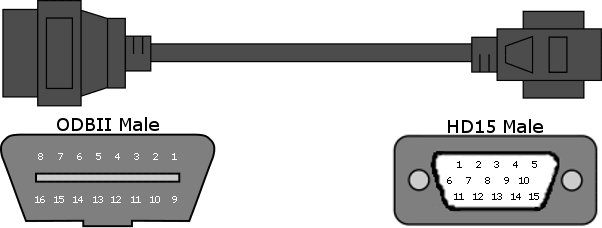
    Rather than re-wire the ODBII port on the car, I was going to create a little 2" cable with M/F DSUB15 connectors between the DSUB15 end of the ODBII cable and the MPVI Pro box. I am going to use a DMM to figure out which pin on the connector is connected to pin16 (unswitched power) on the ODBII port and then insulate it and not pass it through, then use a switched power wire for that pin on the end facing the MPVI Pro unit.

    Since the MPVI Pro box will be within a few inches of my NGK AFX control box (mounted in the glove box), and since I already have a switched power wire ran to that from an open fuse spot in the fuse box at the bottom of the passenger firewall, I would like to use the same wire for this. I can also tie the ODBII chassis ground (and signal ground?), and the EIO ground into the ground wire that I have run for the NGK box, so everything is using a common ground.

    Long story, I know, but I have a few questions. First, is there anything wrong with doing this?

    Second, how much power does the MPVI Pro box pull? I want to be able to fuse this appropriately. The NGK AFX box pulls about 3A max, so I currently have a 5A fuse in that spot.

    Is there a wiring diagram for the DSub15 side of that cable posted online somewhere? I checked through the help and searched the forum, but didn't find anything.

    I am curious which pins are actually in use and which aren't. I see 5 "discretionary" pins on the ODBII side, but do not know which ones GM makes use of. Maybe I could get creative and put the EIO port that I use into the mix to make a quick disconnect of some sort that way I don't have to unplug the green plug when I take the box inside to pull driving logs.

    It looks like "another" tuning product uses a total of 8 wires for their interface:

    1 12 V
    2 CAN High
    3 CAN Low
    4 Ground
    5 CAN (Low-speed)
    6 VPW
    7 ALDL
    8 Ground

    Since the ODBII pinout looks like:

    1 GM CAN (Low-speed, Single-wire)
    2 SAE J1850-VPW Positive
    3 Discretionary *
    4 Chassis Ground
    5 Signal Ground
    6 ISO 15765-4 CAN High
    7 ISO 9141-2 & ISO 14230-4 K-Line
    8 Discretionary *
    9 GM ALDL (OBD-I 8192bps)
    10 SAE J1850-VPW Negative
    11 Discretionary *
    12 Discretionary *
    13 Discretionary *
    14 ISO 15765-4 CAN Low
    15 ISO 9141-2 & ISO 14230-4 L-Line
    16 Unswitched Battery Power

    Then that product is for sure not using ODBII pins 3, 7, 8, 11, 12, 13, and 15...is it safe to assume that HPTuners isn't using those as well? If so, then a quick disconnect should be easy to rig up

    from: http://download.efilive.com/Tutorial...20Tutorial.pdf (citing my source for the pin-out info)
    Last edited by umrjmac; 06-08-2010 at 04:06 PM.
    Kenne Bell Supercharged 2003 Corvette Z06

  9. #9

  10. #10
    Advanced Tuner umrjmac's Avatar
    Join Date
    May 2010
    Location
    Lenexa, KS
    Posts
    301
    Thanks for the link

    Does anybody have any insight on the other questions?
    Kenne Bell Supercharged 2003 Corvette Z06

  11. #11
    Advanced Tuner umrjmac's Avatar
    Join Date
    May 2010
    Location
    Lenexa, KS
    Posts
    301
    I spent a little quality time with my DMM and the HPTuners cable. I couldnt find a pin-out diagram anywhere, so I figured that I would go ahead and post this up to save someone else some time.


    Code:
    ODBII   HD15   Notes
      1       9
      2       1    SAE J1850-VPW+ (Serial Data)
      3       3
      4      13    Chassis Ground
      5    Shield  Signal Ground
      6      11    ISO 15765-4 CAN High
      7       6
      8       8
      9      14
     10       2
     11       4
     12      15
     13       5
     14      12    ISO 15765-4 CAN Low
     15       7
     16      10    Unswitched Battery Power
    Assuming that the ODBII pin usage is consistent between this and the "other tuning app", I have listed out in the "Notes" section what the relevant pins are.

    The older (Gen3 V8 style) stuff just needs pins 2, 4, 5, and 16 (data, ground, ground, and power, respectively).

    The newer (Gen4 V8 style) stuff also needs the CAN High and Low pins.

    (Pardon the code block...i couldnt figure out another way to make table-style data within the bulletin board)
    Kenne Bell Supercharged 2003 Corvette Z06

  12. #12
    Quote Originally Posted by umrjmac View Post
    I spent a little quality time with my DMM and the HPTuners cable. I couldnt find a pin-out diagram anywhere, so I figured that I would go ahead and post this up to save someone else some time.
    Have you verified your pin out diagram is correct for the HPTuners MPVI interface?
    HPTuners support will not supply the pin out configuration for their DB15M (VGA style)connector.
    I need to fabricate some right angle OBDII connectors to eliminate the entanglement from a cable hanging between your legs while driving.

  13. #13
    Advanced Tuner umrjmac's Avatar
    Join Date
    May 2010
    Location
    Lenexa, KS
    Posts
    301
    Quote Originally Posted by wstaab View Post
    Have you verified your pin out diagram is correct for the HPTuners MPVI interface?
    HPTuners support will not supply the pin out configuration for their DB15M (VGA style)connector.
    I need to fabricate some right angle OBDII connectors to eliminate the entanglement from a cable hanging between your legs while driving.
    I checked it twice, but if I were you, I would just take a DMM with the supplied cable and run a continuity test to doublecheck my work. If you run into any discrepancies, post up here and I'll verify them and update the image, if need be.

    Thanks
    Kenne Bell Supercharged 2003 Corvette Z06

  14. #14
    HPTuners support will not supply the pin out configuration for their DB15M (VGA style)connector.
    I need to fabricate some right angle OBDII connectors to eliminate the entanglement from a cable hanging between your legs while driving.[/QUOTE]

    its just a cable whats the big deal why wont they offer a pin out
    i too would like move my obdII port to the pass side via a 90deg thin connector or removing and un pinning and re pinning the connector after its been extended so i dont break it while driving
    2002 Z06-408LQ4 583RWHP 496RWTQ on E85 / 919RWHP 895RWTQ @300 shot

  15. #15
    Advanced Tuner Phantom's Avatar
    Join Date
    Jan 2008
    Location
    Louisville KY
    Posts
    200
    Or the easiest thing to do instead of building a connector is to get an obdII extension or splitter. Then remove the obdII port mount and place it above the kick panel use the splitter to direct it over to the center console area and then use it.

    02 VW Golf

    98 Bonneville SSE
    03 Grandprix GT
    EcoModder