Page 1 of 2 12 LastLast
Results 1 to 20 of 39

Thread: Please Help Define Injector Timing

  1. #1
    Tuner in Training
    Join Date
    May 2008
    Posts
    24

    Please Help Define Injector Timing

    HPTuners Staff, please help:

    Been fighting with light throttle surge in a 416 with l92 heads / L76 intake transplanted into an 01 LS1 Camaro. VE table is spot on as dialed in by WB and all injector values are taken from the Holden Commodore 6.0. It surges in OLSD, OLMAF, CLSD and CLMAF, so it isn't prop fueling, issues with closed loop or a bad MAF. I have ruled out spark timing as well through much experimentation. The only thing left is injector timing, for which HP Tuners lists the following tables. I opened up my stock tune using EFI Live’s demo software. I couldn’t find an Injection Boundary table, but I found the two others. I have included EFI Live’s definitions in parentheses to help shed light on these tables.

    Injection Timing Boundary: Fuel injection delivery boundary as number of reference periods after TDC. (Stock value = 6.5)

    Normal Injection Target vs. ECT: The end of injection target measured in reference periods after the injection boundary that the normal injection pulse should finish. (Stock values range from 2.55 at low ECT to 5.55 at high ECT) [EFI Live: This table will offset the actual opening of the injector referenced to the reference pulses and engine coolant temperature. {B3702}]

    Makeup Injection Target vs. ECT: The end of injection target measured in reference periods after the injection boundary that the makeup injection pulse should finish. (Stock values all at 5.55) [EFI Live: This table modifies the timing of the additional pulses that maybe required after the {B3702} Injection Timing offset limits are reached. These values should not exceed those in {B3702} Injection Timing. {B3703}]

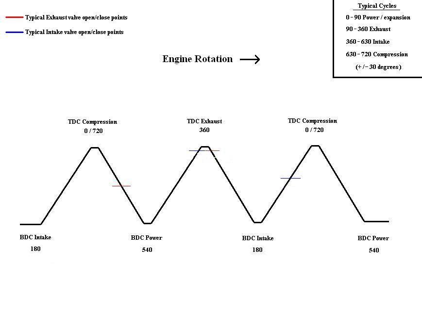
    Based on HPTuners mouseover definitions, the stock Injection Timing Boundary is 6.5/24*360=97.5 deg ATDC, and the stock Normal Injection Target vs. ECT further adds 5.55/24*360=83.25 deg ATDC, for a total of 180.75 deg. This is confusing since I thought the LS1 uses end of pulse to back calculate when to start the pulse. Based on EFI Live’s definitions, the Normal Injection Target vs. ECT table actually subtracts from the Injection Timing Boundary to define when the injector opens. That is, the injector fires at 97.5 deg ATDC – 83.25 deg = 14.25 deg ATDC. This last definition makes more sense as the stock LS1 cam begins opening the intake valve @ 0.050” around 14.25 deg ATDC.

    Could you please help us understand what these tables do and how they interrelate? I have a suspicion some of the definitions aren’t quite right. What do I need to change to get my injectors to open about 25 crank degrees earlier than they currently do? Please also confirm that one reference period is 1/24 crank revolution.

    Thanks

  2. #2
    HP Tuners Support
    (foff667)
    Bill@HPTuners's Avatar
    Join Date
    Jun 2004
    Location
    Hailing from Parts Unknown
    Posts
    28,268
    Here is some information on the topic http://www.hptuners.com/forum/showth...ight=injection both Chris & Greg(eficalibrator) give information on the values.

    Hopefully this helps.
    It doesn't have to be perfect, it just needs to be done in two weeks...

    A wise man once said "google it"

  3. #3
    Tuner in Training
    Join Date
    May 2008
    Posts
    24
    I actually read the post in the link you attached many times over the weekend trying to make sense out of how these tables work.

    I understand that the Injection Timing Boundary table is the base reference point. What I don't understand is the Normal Injection Target vs. ECT table. Does it subtract from the Injection Timing Boundary table to define an injector firing start point, as the EFI Live definition seems to suggest? Or does it add to the Injection Timing Boundary to define a point that is yet further in positive crank degrees from TDC for the ECM to back calculate from, as the HPTuners mouseover seems to suggest? I believe the first is correct, but cannot be 100% sure based upon the available definitions.

    Also, one crank reference period is 1/24 revolution for 24X reluctir engines. Correct?

  4. #4
    the values are End of Injection targets. The normal target vs coolant is when the main or first injection pulse should finish *after* the boundary. The hardware then calculates when to open the injector to deliver all the fuel at the current pulsewidth before the end of injection target. By that logic, to make the injectors open sooner (finish earlier) you would make this value smaller.

    The way i see it is the numbers come out to injecting fuel during the intake stroke high airspeeds ie. when the intake valve is open (to maximize atomization and minimize puddling at the valve & wall wetting). The End of Injection would then occur sometime before the intake valve closes, not opens. eg. sometime around 180deg ATDC or before.

    The way i read it efilive's definition is the same as ours.

    Chris...
    I count sheep in hex...

  5. #5
    Tuner in Training
    Join Date
    May 2008
    Posts
    24
    Thanks for the reply. Last light I went through several flashes with differing values in the Normal and Makeup tables. What I found was that the car does not like the values reduced.

    Initially, I reduced all values in both the Normal and Makeup tables to 1.6 (24-deg) below stock, thinking that this would make the injector fire earlier. This made the car run noticeably worse. At WOT, power was noticeably down and the intake sound was a deep and sickly bog. Next, I increased all values in both the Normal and Makeup tables to 1.6 (24-deg) above stock. This made the car run better. Throttle response was snappier and the WOT intake sound was nice, deep and robust.

    So, if Chris’s definition is correct (i.e. the values are end of injection targets), changing the EOIT from stock’s ((6.5 boundary + 5.5 Normal)/24)*360=180-deg ATDC to ((6.5 Boundary + 7.1 Normal)/24)*360=204-deg ATDC actually made the car run better. The difference was noticeable.

    Anyone have any idea what is going on here? According to my thinking, a larger than stock cam should want the injector to fire earlier to put it in sync with the intake valve opening and the initial rush of air into the cylinder. For this engine, firing the injector later made it run better. Cam is 228/232 114+4.

  6. #6
    Senior Tuner eficalibrator's Avatar
    Join Date
    Mar 2006
    Location
    Detroit
    Posts
    1,023
    Quote Originally Posted by Chris@HPTuners
    ... By that logic, to make the injectors open sooner (finish earlier) you would make this value smaller.
    Quote Originally Posted by Matt-B
    What I found was that the car does not like the values reduced...
    ...Anyone have any idea what is going on here? According to my thinking, a larger than stock cam should want the injector to fire earlier to put it in sync with the intake valve opening and the initial rush of air into the cylinder. For this engine, firing the injector later made it run better. Cam is 228/232 114+4.
    Bigger cams can exhibit a phenomenon known as "short circuiting" of the fuel where the vaporized fuel cloud gets blown right out the exhaust valve during overlap. To reduce the chance of this happening, one can DELAY the end of injection event so that there is less chance of this happening. To accomplish this, you would effectively INCREASE the values.

    The downside to this is that you don't give the fuel as much time to evaporate, so combustion quality may suffer. It's still better than the misfire associated with dumping the fuel out the exhaust instead of trapping it in the cylinder. Also, since the fuel is now being injected across an open intake valve (it's normally early enough that it hits the closed valve), there is an opportunity for bore wash at low speeds until port velocity is sufficient to carry the fuel charge dominantly. For this reason, we only try to delay as little as possible to avoid the short circuiting.

    I bet you don't find info like that in your average class or internet post.

  7. #7
    Tuner in Training
    Join Date
    May 2008
    Posts
    24
    Thanks. Fascinating information. The final values I ended up with were more conservative, only adding 1 across the board to both the Normal and Makeup tables. This seemed to provide as much practical benefit as the larger 1.6 addition I originally tried. Adding 1 to these tables should effectively delay the injector opening 1/24*360=15-deg. Do you think this is ballpark OK?

    And I agree, you are not going to find info like this in your average calss or Internet post.

  8. #8
    also remember that the dominating effect with your new cam is probably not tuned exhaust scavenging/overlap. It's just the simple increased duration and likely higher and more agressive lift increasing the volumetric efficiency (ie. airflow), compared to the stock cam.

    Like most things injector timing could be optimized for torque on an engine dyno, rather than the many other probable optimisations for the stock injector timing. The LS2 hardware is a little more flexible in this regard as well.

    It's interesting stuff indeed and something very few tuners play with, and no doubt in OEM-land is mostly optimized for emissions and cold start driveability (if at all).
    I count sheep in hex...

  9. #9
    Advanced Tuner
    Join Date
    May 2004
    Location
    AUSTRALIA
    Posts
    839
    One could scope what is happening with injection timing in relation to crank angle and spark. Firstly, to determine what TDC actually means. Secondly, to determine what relaised offsets moving these values around has.

    The stock LS1 injects onto the back of a closed valve, and I usually interpret TDC to reference the peak of the compression stroke, not exhaust stroke. What phase does the LS1 use?

    The reluctor wheel doesn't generate evenly spaced pulses, so 2x crank pulses could work out to be a physical duration of anywhere from 15* to 30* crank rotation.

  10. #10
    Tuner in Training
    Join Date
    Oct 2008
    Posts
    11
    I know this is a very old thread, however I think it was just getting to a point that would allow a tuner to enter a boundary value based on known valve events. The two missing components that I see are:
    1- Is the TDC that the injection boundary follows compression TDC or overlap TDC?
    -If this is based on Compression TDC, that would put the injection event during the middle of the exhaust stroke (exhaust valve open, intake valve closed)
    -If this is overlap TDC, the injection event would occur while the intake valve is wide open, on it's way back closed. The exhause valve would already be closed and "short circuiting" would not occur. I know that it has been stated here that the ls1 in stock configuration injects into the back of a closed intake valve. If that is the case, this "overlap TDC" basis does not appear to be correct.

    2- How long (in degrees of crank rotation) is a "reference period". If it is only15 degrees(360/24tooth reluctor), there is no way that you could do anything but inject to the back of a closed intake valve, regardless of the Boundary (max 8) and EOIT(max 8) settings. (assuming that boundary is based on compression TDC)

    In my scenario, I'd like the injection to finish at around 20 degrees after overlap TDC (exhaust valve just closing, intake about 1/3 open) which would make the sum of the boundary and eoit=26.21 (if it is based off of compression TDC and each "period" is 15 degrees.

    Can anyone clarify the TDC reference period and "period" value in crank degrees? Thanks in advance
    LS6 - LA Enterprises 6.3" rods - LPE/Lunati coated pistons 11.75:1 CR - XER cam 236/242 +3 110 - Magnum rollers - 1.8 rockers
    Ported LS6 Heads - Ported fast 90mm intake - 90mm Holley TB - Deka 60lb injectors - 4" CAI - 1.75" ceramic longtubes
    T56 - SPEC 3 clutch - Fidanza Fly - 4.10 8.8" Ford IRS - DSS axles - HP Tuners

  11. #11
    Tuner in Training
    Join Date
    Oct 2008
    Posts
    11
    Found this in a holden manual. Makes things a little more confusing. I do not know if reference period is 3, 12, 15, degrees or a multiple. They had a graphic of the Crankshaft Position signal and the pattern is very unique.

    The reluctor wheel is mounted on the rear of the
    crankshaft. The 24X reluctor wheel use two
    different width notches (12° and 3°) that are 15°
    apart. This pulse width encoded pattern allows
    cylinder position identification within 90 degrees of
    crankshaft rotation. In some cases, cylinder
    identification can be located in 45 degrees of
    crankshaft rotation. This reluctor wheel also has
    dual track notches that are out of phase. The dual
    track design allows for quicker starts and accuracy.


    Also found this elsewhere online:
    The crankshaft reluctor wheel is mounted on the rear of the crankshaft. The wheel is comprised of four 90-degree segments. Each segment represents a pair of cylinders at TDC, and is further divided into six 15-degree segments. Within each 15 degree segment is a notch of 1 of 2 different sizes. Each 90-degree segment has a unique pattern of notches. This is known as pulse width encoding. This pulse width encoded pattern allows the PCM to quickly recognize which pair of cylinders is at top dead center (TDC). The reluctor wheel is also a dual track-or mirror image-design. This means there is an additional wheel pressed against the first, with a gap of equal size to each notch of the mating wheel. When one sensing element of the CKP sensor is reading a notch, the other is reading a set of teeth. The resulting signals are then converted into a digital square wave output by the circuitry within the CKP sensor.

    Maybe if someone knew when an injection cycle actually happens (osciliscope) on a stock ls1 with known boundary settings we could calculate what the "reference period" really is.

    I wonder if a reference period is actually 45 degrees since "boundary" has a max of 8.... =360?
    Last edited by tinkerguy; 04-22-2010 at 05:40 PM.
    LS6 - LA Enterprises 6.3" rods - LPE/Lunati coated pistons 11.75:1 CR - XER cam 236/242 +3 110 - Magnum rollers - 1.8 rockers
    Ported LS6 Heads - Ported fast 90mm intake - 90mm Holley TB - Deka 60lb injectors - 4" CAI - 1.75" ceramic longtubes
    T56 - SPEC 3 clutch - Fidanza Fly - 4.10 8.8" Ford IRS - DSS axles - HP Tuners

  12. #12
    Tuner in Training
    Join Date
    Oct 2008
    Posts
    11
    Anyone have any additional thoughts for the discussion?
    LS6 - LA Enterprises 6.3" rods - LPE/Lunati coated pistons 11.75:1 CR - XER cam 236/242 +3 110 - Magnum rollers - 1.8 rockers
    Ported LS6 Heads - Ported fast 90mm intake - 90mm Holley TB - Deka 60lb injectors - 4" CAI - 1.75" ceramic longtubes
    T56 - SPEC 3 clutch - Fidanza Fly - 4.10 8.8" Ford IRS - DSS axles - HP Tuners

  13. #13
    Advanced Tuner printmanjackson's Avatar
    Join Date
    Nov 2009
    Location
    USA
    Posts
    412
    found this thread with good info:

    http://forum.efilive.com/showthread....jection-timing

  14. #14
    Advanced Tuner printmanjackson's Avatar
    Join Date
    Nov 2009
    Location
    USA
    Posts
    412
    After reading that thread I decided to try and see what moving the EOIT referance would do leaving the tune is SD and see what it would do to the AFR. I tune in lambda and I first made sure I had a stable base to compare to. I logged about a 5 mile trip that included several stops. After I had my base I made the same trip with every change to the EOIT and compared the AFR differance.

    my cam is 226/230 .598/.600 112+2
    according to the specs this cam has overlap of 53 at .006 and 4 at .050

    The first change was to add 15% to the EOIT. The Lambda did not move with this change.

    The next change was to add 18% the the original EOIT number. The Lamnda moved very little with this change. I noticed maybe a few spots of maybe 1% in the 800 rpm range but nothing the the others.

    The next change was to add 20% to the original EOIT number. This change made the idle go rich right off by 2%. The upper RPM's showed maybe 1-2%.

    From what the AFR shows I need to use 15%-18% added to the EOIT number for my tune. I'm going to see if the 18% corrects my rich idle and if not I can back it to the 15% and compare.

    Compare the first two columns with each histogram, that is where most of the change shows up.
    Last edited by printmanjackson; 09-17-2010 at 11:49 PM.

  15. #15
    Tuner in Training
    Join Date
    Jun 2008
    Posts
    31
    very interesting thread

  16. #16
    Tuner in Training
    Join Date
    Oct 2008
    Posts
    11
    Did you make the percentage increases to the Injection Boundary value or Normal injection target table? Any differences in perceived idle quality or unburnt gas smell? Thanks!
    LS6 - LA Enterprises 6.3" rods - LPE/Lunati coated pistons 11.75:1 CR - XER cam 236/242 +3 110 - Magnum rollers - 1.8 rockers
    Ported LS6 Heads - Ported fast 90mm intake - 90mm Holley TB - Deka 60lb injectors - 4" CAI - 1.75" ceramic longtubes
    T56 - SPEC 3 clutch - Fidanza Fly - 4.10 8.8" Ford IRS - DSS axles - HP Tuners

  17. #17
    Advanced Tuner printmanjackson's Avatar
    Join Date
    Nov 2009
    Location
    USA
    Posts
    412
    Quote Originally Posted by tinkerguy View Post
    Did you make the percentage increases to the Injection Boundary value or Normal injection target table? Any differences in perceived idle quality or unburnt gas smell? Thanks!
    no, the boundary stays the same. the changes were made in the "normal"and "make up" tables.
    '02 Corvette
    LS6, MN6, LT's/X pipe and TI's, Honker CAI, AI 243 heads, PatG Custom Cam, FAST 102, LS2 TB, Red Top inj, HPTuners & NGK/AFX

  18. #18
    Advanced Tuner
    Join Date
    Sep 2010
    Location
    FL
    Posts
    374
    Alright, let me take a shot at figuring this out. First, let me define a diagram for you to follow.


    Ok, now it seems to me that this format seems to fit Fords. But with the GM software, instead of counting in degrees from 0 (TDC compression), I think they start with TDC exhaust as 0. So where 360 is on my chart, that might be 0 and 540 on my chart might be 180.

    If you take 360 crank degrees, and divide by 24 teeth (reluctor wheel), you get 15 degrees per tooth. If we define Boundary as just that, a boundary... a fence... a limit, and use that as a reference point from which to find our target, then a boundary of 6.5 would give us 97.50. To keep us on the same playing field as the numbers already on the chart, lets just add 97.50 to 360 = 457.50.

    Add the normal injection target vs ECT of 5.55 to get 5.55 x 15 = 83.25. HPT says this is reference periods AFTER boundary. So add that to our 457.50 boundary to get 540.25. That's pretty much exactly BDC on the intake stroke. The intake valve would be wide open for about 2/3 of it's duration at this point. Seems pretty late to me for end of injection.

    What if HPT got it wrong in the description? Could it be that it's BEFORE the boundary? 457.50 - 83.25 = 374.25. That's just after TDC on the exhaust (overlap) cycle. Looking at the Fords tables, many of their tunes come up in the 280 - 420 range, with 380 being typical. So this might pan out.

    Let's look at another tune, a 2010 Camaro 6.2 auto. These tables are slightly less mysterious. The injection boundary is actually defined as 513. That fits nicely near the bottom of the intake stroke on my map. The definitions here call for the normal injection target vs ECT to be BEFORE the boundary! (Hmmm.... this goes back to what I mentioned above about the description being wrong?). So the ECT calls for 110 before the boundary if the engine is warm, and as much as 245 before the boundary if the engine is very cold. Looking at the 110 warm value, we're now at 513 - 110 = 403.

    Then there's an injection vs RPM table that calls for pulling 0 at idle, 62 @ 3000 rpm, and 93 @ 4000 rpm. Sticking with WOT/high rpm focus, we'll take the 403 - 93 = 310. That puts us 50 degrees BTDC on the Exhaust (overlap) stroke. In other words, it's starting and ending the injection pulse sooner... before TDC and before the intake valve opens.

    Now forget about duration @ .050. Think in terms of advertised duration for injector delay focus. There is some overlap, even on the mildest of cams. And even more on hot factory cams. So the exhaust valve is likely open until just past TDC, while the intake valve is likely opening just before TDC, or close anyway. One factor I'm not considering here is VCT on the 2010 camaro scenario. I haven't looked into whats happening with cam angle yet.

  19. #19
    Advanced Tuner
    Join Date
    Sep 2010
    Location
    FL
    Posts
    374
    Now here's one more shot. Greg's book (pg 52, EM:AT) has a diagram with numbers laid out differently than what I came up with for the Fords. It looks like this:


    If you consider the same numbers from the above examples, the 2010 camaro had a 513 boundary, 403 warm at idle, 268 cold at idle, and 310 warm/high rpm.

    The LS1 setup had 457.50 plus 83.25 = 540.25, OR 457.50 minus 83.25 = 374.25.

    Cmon Greg, I know you're out there! Enlighten us.

  20. #20
    Senior Tuner eficalibrator's Avatar
    Join Date
    Mar 2006
    Location
    Detroit
    Posts
    1,023
    The big problem with trying to call out an exact point of EOI, EVC, or IVO in crankshaft degrees is that it must be referenced to something. From one manufacturer to another, one ECU family to another, or in some cases one model year to another, the reference point can change. So "540 crank angle" is not always the same point when comparing two different systems since one might be referencing TDC Compression while another might be referencing a valve event.

    What's important is that you recognize the trend on EOI offsets and know which direction you would want to push things if you were to change hardware. Adding more cam overlap opens the door for short circuiting, so we typically want to shift the EOI by some amount to minimize this. Exactly how much shift is necessary becomes subjective, so it's tough to say "just add x units and it'll be perfect." But I can look at the system and get a feel for whether it's degrees of crank angle or reference periods or whatever and still have a good idea of what kind of shift I might want to improve combustion stability. That's what I'm really after anyway. So as long as I shift things such that fuel is burning INSIDE the cylinder, we can move on to other calibration tasks.