Well I got the PLX narrowband simulation working perfectly fine now. Using a PLX wideband controller and HPT tuner this is how I did it in my 2000 Buick Regal.
Being I have a stainless exhaust system I didn't want to deal with having to weld another bung into my exhaust. Also with the size piping and being I have a catalytic converter I have very limited space to even put another bung hole. So I took my stock 02 sensor out and put the wideband in its place while using the PLX to simulate the narrowband signal.
Normally with the PLX unit if you are going to be simulating the narrowband they say to use resisters to simulate the heating of the 02 sensor. This is so you don’t get any error codes from the PCM. Well being I have an HP tuner I decided not to do the resister simulation and just deleted the error codes dealing with the heating of the 02 sensor which worked out perfectly fine.

Labeled #1 in the picture above is the power/ground for the PLX controller. My 2000 Regal has an accessory power drop. So I connected the units power/ground wire to that.
The PLX unit has a 4 wire Analog connector which is labeled #2 in the picture above. Starting at the top left and working my way across the 4 pin connection is like this
Pin 1 (Top Left) - 3.3 Volt I think it used for hooking up PLX WB gauge for power?
Pin 2 (Top Right) - Narrowband simulation which goes to your cars stock 02 purple signal wire (on GM cars)
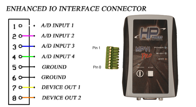
Pin 3 (Lower Left) - Ground which I connected to #5 ground port on the HP tuners EIO connector which is pictured below
Pin 4 (Lower Right) - WB Signal output that I connected to #1 A/D Input 1 on the EIO connector pictured below
When I first powered the unit up the wideband function was working on my car. However the narrowband simulation was not working and according to the HP tuner the 02 voltage was a constant 447 instead of cycling on/off. Originally the only wire I touched on the cars stock 02 harness was the purple signal wire which I connected to the narrowband simulation spot on the PLX controller.
After some research and messing around with the setup I figured out the problem.
If you look at the picture above that is what a GM 4 pin heated 02 sensor connector looks like.
Here is the pin out information from my GM service manual:
Pin A (Tan) = Heated 02 sensor 1 Low (Ground for 02 signal)
Pin B (Purple) = Geated 02 sensor 1 Signal (Signal from 02 sensor)
Pin C (Black) = Ground (Ground for heated 02 sensor)
Pin D (Brown) = Fused Output - Ign 1 (Power for heated 02 sensor)
Like I said above I only touched the Pin B purple signal wire on the original 02 harness. However I found out that Pin A the tan color wire is the ground for the 02 signal (the purple wire). So pretty much because I didn’t have that Tan wire grounded the 02 signal circuit was not complete. So I connected Pin A the Tan wire to Pin C the black wire which grounded the tan wire out. I left Pin D Brown wire alone because I am not using the heated 02 circuit anymore.
Break down of what I said above:
1.) Pin B Purple wire goes to Narrowband input on PLX Controller
2.) Pin A Tan wire goes to Pin C Black wire to ground 02 signal
3.) Pin D Brown wire is left disconnected unless you do resister simulation
After grounding that Tan wire out my Narrowband 02 voltage in my HPT started cycling on/off. Now I can finally start wideband tuning my car!
I hope this guide helps some people out if they want to run the narrowband simulation using the PLX wideband unit.


 Reply With Quote


 Thank u so much for ur sharing.