Results 1 to 7 of 7

Thread: help with LM-1 interface calibration

  1. #1
    Tuner 04snake's Avatar
    Join Date
    Sep 2006
    Location
    Upstate NY
    Posts
    75

    help with LM-1 interface calibration

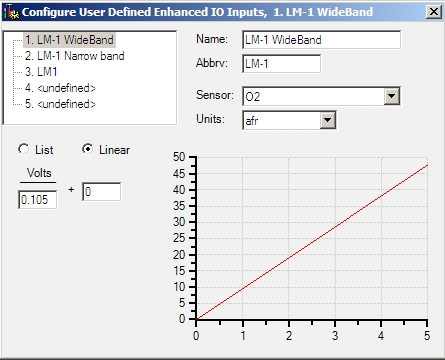
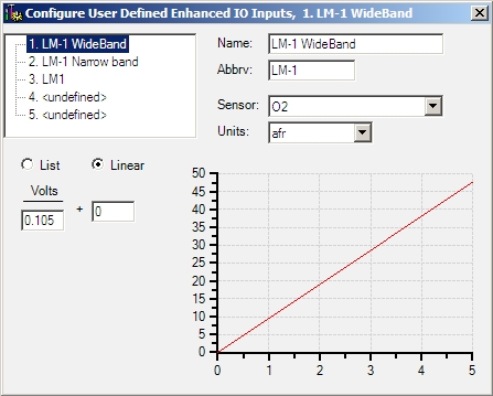
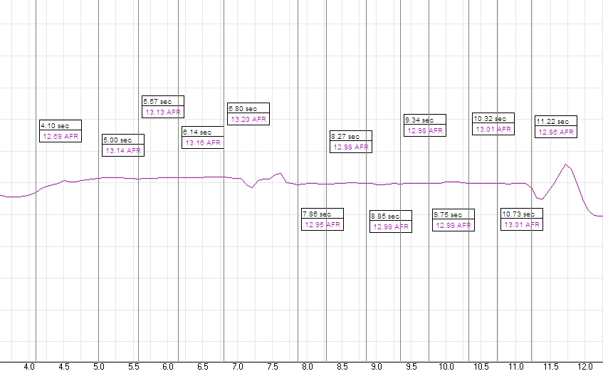
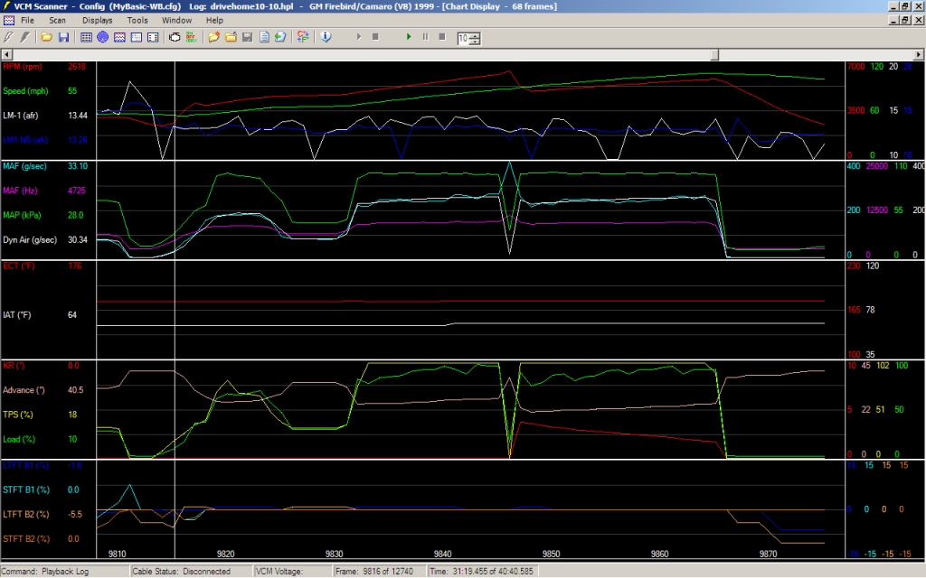
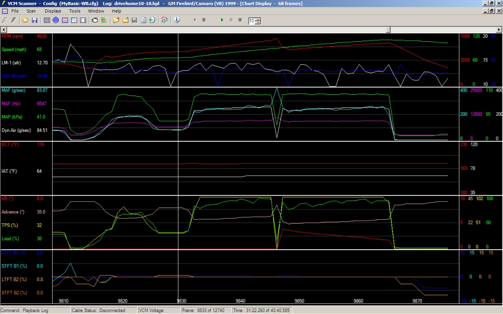
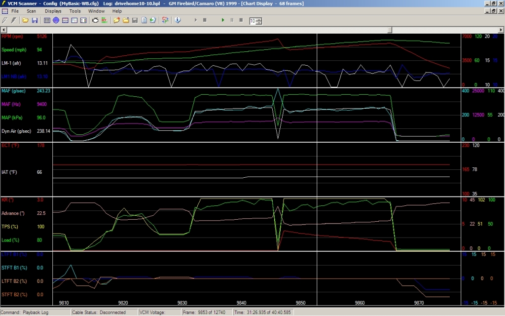
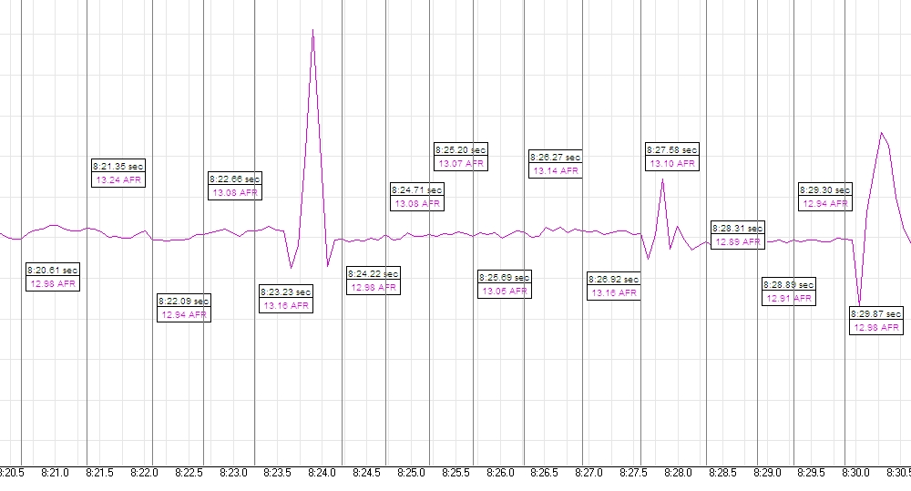
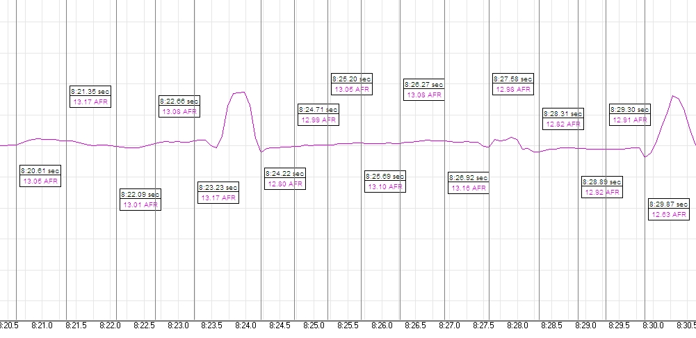
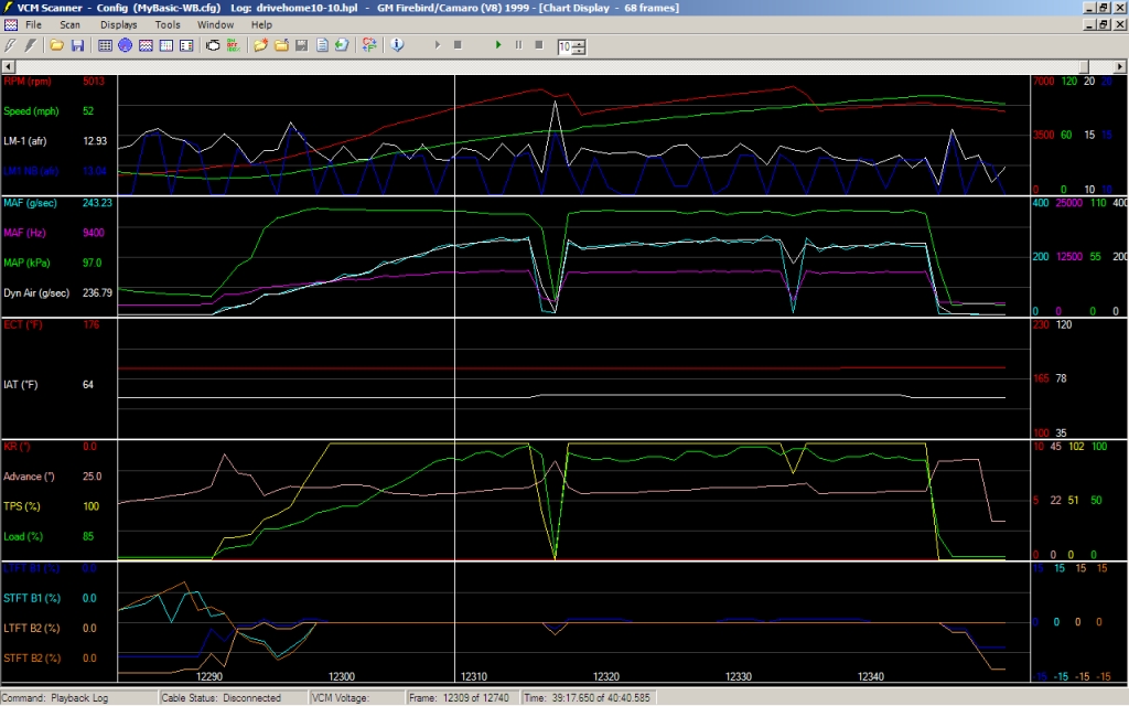
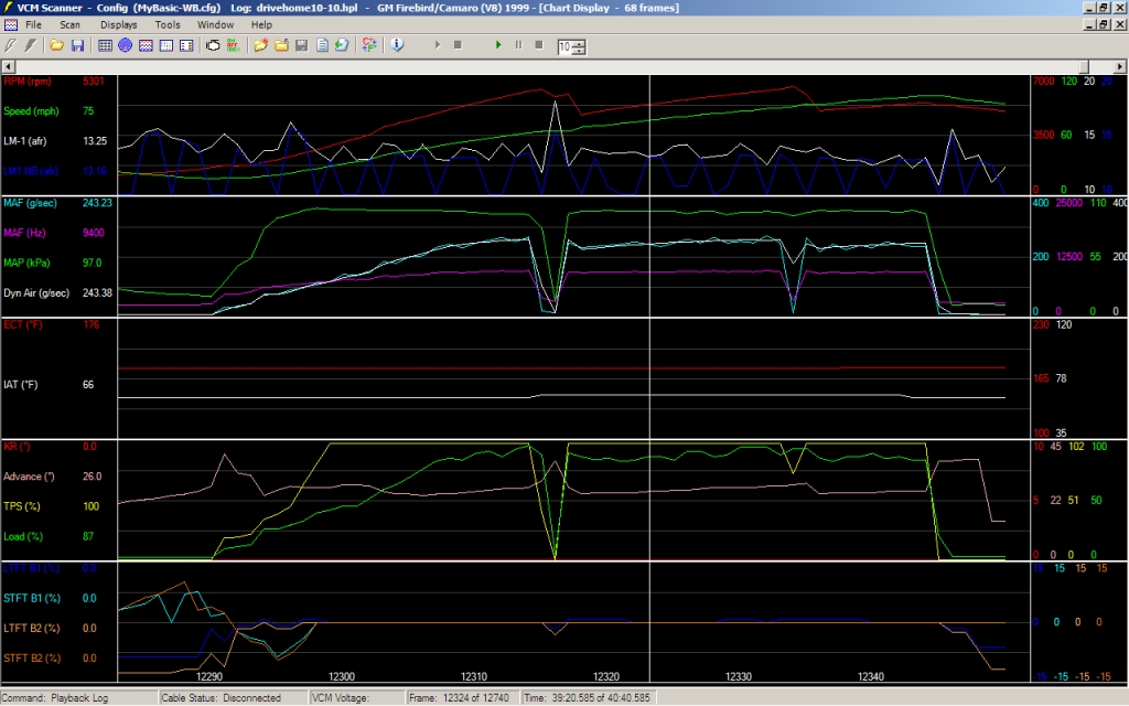
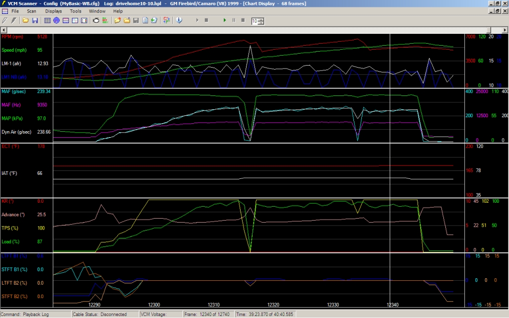
    I used the pre-defined LM-1 input and it is showing 13.1 when the LM-1 is reading Lambda. I am going to try some of the other pre-defined configurations and if I have to define my own calibration so be it.

    Any suggestions, I see I can't update the predefined to tweak it, maybe I'm missing something here?

  2. #2
    Tuner 04snake's Avatar
    Join Date
    Sep 2006
    Location
    Upstate NY
    Posts
    75

    my problem with LM-1 solved

    Hey Keith, what formula do you pre-configure the scanner with for LM1 input? I saw one floating around the net V/.5 + 10 which seems close to what you set-up but mine isn't working with that at all, not even close for either output1 or the second output channel. I got mine to work on both my channels but I had to add a tweak to the LM-1 programmed voltages for both the output1 and output2 (they are different). I finally got off my tired lazy butt and plugged my laptop into the LM-1 and looked at it's factory programming. I also found the configuration I used to hook my SCT Raptor datalogger to output1. It got me close but it was still .9 of a point too lean at Lambda so I think the referencial grounds are in a snit. No worries, that would just require a connection specific calibration, not hard with the Voltage map in front of your face. The LM-1 output1 is actually a Narrow Band simulator, funny I noticed it acted crazy during shift spikes and that was because that output measures between 8 and 16 only, so a lean spike during shift would look like it was going off the scale, if it hit 16.

    here is the formula I used in the Raptor:


    here is the LM-1 factory calibration for output1, I could have changed it here, but then the raptor would be off:


    here is the LM-1 factory calibration for output2:


    this is the "real" wideband output, basically 1 Volt=10AFR and 2 Volts=20AFR, so multiplying it by 10 should be all you need, but I had to add 5% (V/.105) for whatever reason because Lambda was around 1.56 V (not 1.47) but then it worked fine and without some constant adder to fix Lambda, it actually has the proper full wide range.


    I need some more tweaking of the NB output1 and then I should have both right on the money.

    Not sure if I am the only one with an older LM-1 instead of a LC-1, who knows, nobody else seemed to have the same problem when I was searching but maybe this might help someone else searching in the future?

  3. #3
    Tuner
    Join Date
    Feb 2005
    Location
    Winnipeg, MB
    Posts
    96
    I have the same problem, but don't have access to an enchanced cable right now to troubleshoot, I'll be watching this very carefully.

  4. #4
    Tuner 04snake's Avatar
    Join Date
    Sep 2006
    Location
    Upstate NY
    Posts
    75
    OK, I finished my testing and I was mistaken, output1 from the LM-1, the NB simulator output channel (0-5V) according to the manual works with the same formula that works for the Raptor datalogger, so it seems the output2 channel (1-2V), the one I hadn't used before is the only one that doesn't match the LM-1 default factory calibration, but my 5% correction nailed it pretty good. I had to do a test of my final MAF correction, so on the way home from work I did a 3rd-4th gear pass of a Carrera and then did a 2-3-4 pull on a new stretch of pavement near my house and gathered all the data.

    Now one additional thing I did to the LM-1 was to slow it down (at full speed it can see actual O2 bubbles) from it's instant updates to 12@second. To do that you would make a serial connection and then change it at this screen, the LM-1 manual walks you through this.


    The LM-1 data representation on the Raptor was always very spikey but I never bothered trying slowing the update rate down, so I'm kinda interested now if that helps the Raptor, a test for another day. My suggestion is to try it both ways for yourself and see if it makes a diff with HPT Scanner. The reason I didn't care enough to experiment with the Raptor is because the LM-1 logging software (Logworks and now Logworks2) always had a better representation of AFR so I used it to get a flat WOT AFR, the input to the datalogger was there as a reference on the same graph with my other pid's so I could study dragstrip passes and analyze things like between shift hesitation, but it was always all over the place. Well the HPT scanner representation is not as bad as the Raptor, but still nowhere near as smooth as the LM-1's Logworks2 software display with no smoothing. On the first highway pull the NB (0-5v) output1 channel was almost smooth, but the output2 channel (1-2v) was all over the place, even though the average looked close. On the second pull with 5 min drive in between the LM-1 NB channel (output1) was all over the place and the other output2 channel (1-2v) was better? WTF? I suggest logging both the channels if you have the spare pids, else stick with the one that works best for you. Maybe the LM-1 manual has the outputs listed backwards, I mean a 5 volt range seems less like a traditional O2 sensor as oppossed to a 1 volt range but I labeled them as the manual desribed them, just think of output channel 1 and output channel 2 and don't get confused by "NB" and "WB", I just had to keep them straight so I labeled them from the manual description.

    now I showed above how I configured the Raptor for output1 (0-5v) [ (Volts * 1.6) + 8 ) but you have to convert that to [ (Volts / x) + y ] for the HPT:


    Once again here is my configuration for LM-1 output2 channel with my 5% fudge factor that seemed to nail it pretty good:


    Now for the comparisons, first lets look at the LM-1 Logworks2 display of me bitch slapping an older Porsche with a Q-tip at the wheel (3rd to 4th):


    the above graph is NOT smoothed, now I am sure the Logworks2 software does some magic, but below is the type of AFR plot you see from a dyno pull, they are always smoothed. Below I applied the lowest level of smoothing in Logworks2 (.25 sec smoothing):


    Now compare that to the HPT scan with both the LM-1 channels I configured and displayed on top of each other (Blue=output1/white=output2). They are pretty close to what the LM-1 is displaying and logging, maybe a hair leaner and spikey, but close enough to plunk into histograms, too bad I already finished my AFR tuning:


    My second AFR test was from a 20mph roll, 2 shifts, 3 gears with the wife holding on for dear life (she hates when she gets involved in testing!) and it was pretty typical; AFR a tenth or 2 leaner in the lower gears and when I ran out 4th it was right where I wanted it, flat as a pancake 12.9-13.0 without any smoothing.

    First the LM-1 logs without smoothing:


    Then smoothed for comparison:


    now the HPT scans, the only thing wierd is that now output channel 1 (labeled NB and blue) is all over the place but the 1 volt (1-2v) output2 channel is more stable. I have no idea why, just reporting what I saw.


    I hope this helps anyone having the same problem with a LM-1.
    Last edited by 04snake; 10-11-2006 at 08:44 AM.

  5. #5
    Senior Tuner 5_Liter_Eater's Avatar
    Join Date
    Nov 2005
    Location
    Houston, TX
    Posts
    3,968
    I have read several posts that 1/6 second intervals work best w/ the Lx-1's and HPT. Here is the best one. http://www.hptuners.com/forum/showthread.php?t=2941
    Bill Winters

    Former owner/builder/tuner of the FarmVette
    Out of the LSx tuning game

  6. #6
    Tuner 04snake's Avatar
    Join Date
    Sep 2006
    Location
    Upstate NY
    Posts
    75
    Quote Originally Posted by 5_Liter_Eater
    I have read several posts that 1/6 second intervals work best w/ the Lx-1's and HPT. Here is the best one. http://www.hptuners.com/forum/showthread.php?t=2941
    thanks for the link!!

    I will have to try 1/6 sec, I could stand a little more smoothing. I'm surprised I didn't see that with my searches but I wasn't looking for a sampling interval fix. What really interests me is what the Raptor inputed AFR looks like when I re-tune my cobra for N2O but since it isn't as advanced as HPT, you use pen and paper to recurve the MAF transfer table, no histograms, but it still would be nice to see something that didn't look like a earthquake on a seismograph. I know I am coming to the dinner table late and most of these things you guys have already discovered, but there is a fresh supply of noobs like me jumping on all the time so I thought they might be interested if I shared what I saw.

    - stu

  7. #7
    Tuner
    Join Date
    Feb 2005
    Location
    Winnipeg, MB
    Posts
    96
    Great info, now I just need time to try it out for myself.