Anywhere in my car that a function does not exist because the OEM ecu cannot or does not capable,
I use the basic microcontroller as Arduino,
For example there is no transmission temp output (GAUGE) from the OEM ecu or transmission fan temp activation,
So I take Arduino NANO ($20?) and a $.05 temp sensor 1/8" NPT from ebay and utilize voltage divider to interpret resistance (1 wire temp sensor into ADC voltage input)
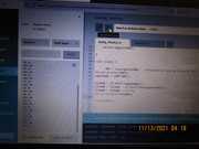
Then measure with multiple thermometers, generate a semi-log curve for resistance:ADC:Temperature, finalize the curve using excel curve fitment (lets see if I have a picture of that... hmm)
Pics! (Open in new tab should give a large picture)


SO now I get Transtemp readout on Display LCD in the car, and I can switch on the transmission fan using Arduino -> Darlington pair (transistors 2N2222) -> Fan Relay -> Fan Activate
Furthermore you can get crazy with it. You can use motion detector for example to determine whether fan is actually spinning or not. You can measure temperature in front of and behind the trans cooler if you wanted using air temp sensors (Very cheap). Same for radiator and underhood temperatures. You could spray water (water drip system is ideal to prevent heat soaking in traffic) Using water detection through transistors to turn the system on and off. Use external PWM drivers to make it simplicity.
And so forth.
SO for your proposed project, simply read how others are doing it. bring in tach signal then use transistors (I recommend darlington pair a 2N2222 for most automotive relays, has been reliable for me) to switch things on and off if the relay is fast enough for the job. Some things you might need a Solid State Relay or some other fancy things, but the idea is the same, using microcontroller to make up for missing features.
https://forum.arduino.cc/t/reading-a...gnal/128761/14


 Reply With Quote

 your 5.3L turbo S14 thread is crazy! Holy crap so much to unpack but damn that is impressive.