Wow this thread is amazing...and I don't think my PCV views agree with anyone here lmao! I love the PCV the system and its intricacies and I agree it is a greatly misunderstood topic. Good luck.


Wow this thread is amazing...and I don't think my PCV views agree with anyone here lmao! I love the PCV the system and its intricacies and I agree it is a greatly misunderstood topic. Good luck.
A standard approach will give you standard results.
My Tuning Software:
VVE Assistant [update for v1.5]
MAF Assistant
EOIT Assistant
That's been my experience with the EFI specialist.Originally Posted by kingtal0n

I detect a chasm forming
I don't mind being a cat with a misinterpreted viewpoint on behalf of gnomes which have never interpreted a bode. If the mind cannot conceive or comprehend something it may seem scary, 'great and terrifying masks' somebody said.
When they stop trying to at least use logic and resort to name calling and trash talking- its a brick wall, muddy entertainment sure- when to swap affecting for chaotic panic inducing depression.
luckily, I type faster than normal humans
I never claimed to be an OEM ECU tuning expert. No where, never no how. I have no interest in learning more than I need to either. The key to utilizing higher education isn't memorizing or learning specific details about a system you won't encounter every day like a job or something. It is the ability to comprehend the potential governing systems of equations for those random system as an infinite series of possible inputs and outcomes without a single real number coming or going.
I never copy and paste and I think its strange people still accuse me that- instantly I can tell more about them like they cannot comprehend that somebody could actually be so well read and can't be bothered to search up the things I say to verify if they exist anywhere else. If I listed the books here it would draw disbelief- If people do not believe, they are not capable, they assume nobody else could be capable either. A folly to be sure and one which place holders your persona to limitations you have imposed on yourself, a self cage. The death of plasticity and end of cellular differentiation is a set form and function for some designed task which may no longer be relevant or useful. Genes which do nothing. Switches that control nothing.
It isn't experience that drives tuning ability. If you learn how computers think and how engines work, you can tune any computer, any engine, they are all the same. I knew how to tune 'hptuners' before I knew it existed. I knew exactly what to do, what the computer would be capable of, how to setup the wires, devices, and achieve my goals; and despite only being able to make sense of about 60% of what it pretends to do I got what I needed and moved on, I have not connected my laptop in years to the open loop 5.3 @ 600rwhp with 250,000 miles that is so clean inside and out. The minimum effort, the laziest possible investment, the most desirable outcome from doing basically nothing. That is experience talking, not higher education. I guess in the end, it takes both and if you are missing something from either you just can't see from a high enough point to make sense of it. That doesn't make it lies, though. I think that is the biggest problem, the lack of comprehension leads to the assumption that something must be false. If I tell you that THP-1 leukemia monocytes can be differentiated into M1 macrophages by the presence of E-coli lipopolysacharides at a concentration in the picomolars- you can easily look that up because its published information. Just like the PCV pressure drop happens at the throttle valve is published information and I have posted the paper from which it can be found earlier in the thread. But people don't read it. They don't care what doctors and engineers and the original systems mathematically and physically do because they cannot be bothered to decipher them or even try to read them I guess. Its like all the information you could possibly need to properly setup the systems around an engine are published but nobody likes to read so nobody ever figures it out, they just copy each other and buy crap they don't need from sales people who take advantage of that ignorance. If they could visualize the pressure difference due to friction in a tube like any good pump engineer and rate of change of pressure for a given crankcase volume they would see it too. But you can't even write a proper formula for those people they just want to copy that 'expert' on the car forum who has '40 years of experience'. Experience is meaningless- You can be doing something wrong for 40 years without realizing it.
I won't ignore anybody and I always forgive you for things you say. But nobody on the internet ever apologizes and nobody ever changes their mind, its too easy to hate and trash talk I guess. I don't expect it to change. But over time the one constant is with persistence eventually many people come around to my teachings, a chasm develops and some benefit greatly by simply having faith and doing a little research.
5.3/4l80e/turbo playthrough
https://www.corvetteforum.com/forums...ge-budget.html
cancer research
https://www.mdpi.com/2306-5354/10/1/96
I noticed you said you put them in the valley plate. Does it matter where in the system the PCV goes or as long as it is in the same directional flow; i should be good?
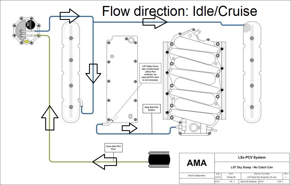
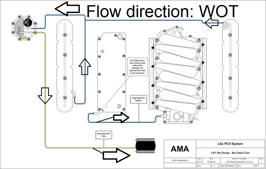
Flow for idle and cruise needs to go one direction, from left to right or right to left.
Flow for WOT pcv needs to go one direction, from left to right or right to left.
Consistent flow with minimal energy losses, no tug of war between sides when they are far apart.
On many engines, the direction changes as the PCV system moves from one to the other. For example
In engines OEM with dry sump like that one that have two high valve cover exit points for WOT pcv there is always a restrictor
48260078d1520021640-valley-cover-pcv-orifice-failure-img_1594.jpg
in one of the valve covers to force the direction of flow in ONE Primary direction at wide open throttle, or a union (connector between covers) to make two valve covers act as one as with an RB skyline engine. Note the valley cover is a union for the crankcase halves and does not have a PCV valve either- there is no PCV valve on that engine, only restrictor orifices in one valve cover and the valley orifice.
We could calculate the possible flow for an orifice to find adequate evacuation rate depending on the available pressure.
Or bottom to top or top to bottom. Some engines like Skyline RB have two equivalent top exits for wot pcv and one side only from left to right for idle/cruise pcv.
The idle/cruise have sufficient kinetic energy input due to intake manifold depression to drive pcv flow despite friction, the WOT side does not.
Therefore WOT side is typically larger or more hoses, as short as possible
My pcv experiments, collected data, recommendations, As measured by me on several engines, and confirmed via GM Powertrain engineer by coincidence
https://www.thirdgen.org/forums/powe...ml#post6466928
You don't need a PCV valve unless you have so much blowby that the orifice can't relieve pressure. Even then it will back flow out the valve covers. Clean air to either valve cover and vacuum on the valley cover is factory configuration. Same diagram as what was by kingtal0n. The problem with your setup is that you've applied vacuum to one of the valve covers.
@KINGTAL0N- Would the routing be the same for a wetsump engine? I have converted to wetsump.
@SIRIUSC1024- The valley plate has the barb on it and I am not sure if it has an orifice in it or full flow. These are the valve covers I have: https://www.proformparts.com/product...kle-ls-engines
LS rob
First determine whether there is a restriction in the orifices, valley cover, or valve covers may contain restrictors. If they do, you might make a critical error in setting up.
Find a valve cover with no restriction. Probably passenger side? This can be your clean air side or wot side. There is no pcv valve in this side. It runs to the intake tube behind the air filter, in front of the throttle valve.
Filter pressure drop controls the pressure of this tube at WOT which can evacuate blow-by from the crankcase which maintains clean oil and engine health. You can measure the pressure using 1-bar map sensor or a sensitive gauge which reads inches of water.
Then, valley cover to intake suction is fine. The valley cover feeds the intake manifold from a source which is located after the throttle valve. This side can use a PCV valve, or a restrictor, If the engine is naturally aspirated it does not need a PCV valve IF it has the restrictor. The valley cover contains a large baffle which can help separate air/oil and appears to function as a fire suppressor as well or they probably would not have removed the pcv valve from this line.
The other valve cover may or may not contain a restrictor. You can tie it into the other valve cover- tie them together- if there is a restrictor in the farther one (driver side) as many dry sump configs will have, but aftermarket covers may not. If there is no restrictor my first trial and error would be to cap it off to test and measure the crankcase pressure at WOT to determine the health and operation of the pcv system. Then, I would measure again with the two tied together, to confirm my suspicion that it will not help with the pressure drop, pressure will be higher. Then, I would try adding an in-line pcv valve to prioritize flow through the closer (passenger side) valve cover and measure one more time. Lowest pressure wins.
added: I don't like the idea of a stagnant cover so I would not seriously consider leaving it capped off even if it does have the best pressure drop, I would probably use the two tied together with a pcv-valve inline between them anyways. Flow direction facing away from the valve cover (leading out of the cover is where you want the flow to go at WOT) This keeps fresh air flowing into the other valve cover with no pcv valve and remember this scenario is ONLY custom for situations where both valve covers have NO restriction orifice.
In other words yes you can use the factory diagram I posted but only if one of the covers and the valley cover have a restriction orifice (or a pcv valve which is basically a restrictor orifice also). Otherwise you may need to take some measurements and get creative. PCV isn't as simple as it seems eh
Last edited by kingtal0n; 09-09-2023 at 07:14 PM.
Ok. I just disassembled the PCV system and blew into the driver side VC, passenger side VC, and valley plate. I was shocked to find out how much effort it takes to blow into the passenger side VC. I looked up the valve covers and posted the link in a previous post. The valve covers are baffled but it doesn't say anything about orifices. Valley plate seemed to flow a little more freely than the VC's but still took some effort and whistled a bit. From this exercise, I feel like i'm not getting enough clean air into the passenger valve cover. Not sure what to do or try next. Is the goal to have a system that flows more easily or do I need it restricted?
https://www.proformparts.com/product...kle-ls-engines
I see. Aftermarket covers, okay. Are you sure passenger side is passenger side? (The valve cover with the oil fill hole mounts on the passenger side of the vehicle.)
Sounds like passenger side cover has a built in restrictor or pcv valve. Could be either- you need to check. Investigate. Look through it or poke with a wire or something? Call the company and ask? Somebody knows something. A PCV will prevent flow one direction, a restrictor will blow the same both ways. Try sucking and blowing (ugh)
Valley cover has a restrictor if there is no PCV valve inline between it and the intake manifold. Again, look carefully, you should see it. Is the hole reduced in diameter?
The important thing is that the valve cover with very easy to blow through gets a direct path to the air intake tube, where it can feed from/to the area just in front of the throttle valve (in front of butterfly throttle blade, on the air filter side).
This is the fresh air supply yes very important.
The valley cover goes to intake manifold suction. Follow what I said above already. If there is a pcv valve inline its fine. IF there is no PCV valve then there must be a restrictor. Either way is fine, but BE SURE you have one or the other. NEVER connect the crankcase directly to intake manifold vacuum without a pcv valve or restrictor as it can damage the crankcase oil seals.
I built this engine from bare block, so i know for a fact that there isn't a PCV inline. Only way there is a PCV, is if it is within the parts I have used. The oil fill cap is on the passenger side. It was surprisingly tough to blow into. It doesn't look like there is much ventilation in the baffling in them. I feel like I need to take them off and drill some small holes into the baffling to allow it to pass more air but not entirely sure that is the route to go. Again, it took more effort to blow into BOTH valve covers but the passenger side seemed more restricted. A puff of reversion air would flow back out of the hose when i stopped. I found a picture of the baffling in the valve covers and have attached it.
baffling.jpg
Last edited by LS ROB; 09-09-2023 at 09:44 PM.
Do you need more help? Would you like a different explanation? I am not sure what you are asking at this point, or just sharing. I can explain differently if you like.
I think I may be able to get it figured with all the attached info.
Thanks!
I am in the midst of re-thinking the pcv on a forced induction Gen4, and wondering what the affect an increase or decrease in crankcase volume would have on PCV efficiency. Currently running a catch can with check valves for boost, but still had some oil in the intake the last time the blower was off.
Regarding crankcase volume (actually within the engine, not the external PCV system); On one hand, increased volume may slow the gases as well as work as an accumulator to dampen pcv fluxuations. On the other hand, you now have a large volume of pressurized gases to remove. My engine does not have a PCV outlet in the valley plate, and with all of the fuel/coolant plumbing right in front of the blower and between the accessory drive, not sure there is much room for one. There could be an opportunity to build something to take up the volume of the valley if that would be beneficial (taking care not to block bay/bay breathing), or even to use a valley plate with the pcv separator used on some engines. I have seen some OE engines that appear to have gone to great lengths to minimize open area under the valve covers, which is why I am wondering on what is best practice in design.
This is an interesting topic, and one that seems to be grossly overlooked in the performance world. I do have a map sensor mounted in the engine bay which I have hardwired to an external input on the MVPI1 Pro, and periodically move the hose to the exhaust, intake, and also the crankcase, to check on backpressure, intake restriction, crankcase pressure. I don't recall what my peak was for crankcase pressure, but a bit higher than I would like when under boost. In other words, it needs improvement in both breathing and oil separation.

Along about 2008 or 2009 after the introduction of DOD the engines started burning a lot of oil. Had nothing to do with the ventilation system but that's what the engineers went after first due to oil in the intake plenums. They wound up gluing the baffling and relocating the breather holes in an attempt to fix the oil consumption. It was then decided that the problem was the lifters, which they did have problems from time to time with spraying oil - you can run the engine with the covers off to see if you have this problem. If you do one lifter will spray oil about 1 foot or more and this will bypass the baffle. Problem actually wound up being the oil return in the pan causing oil to whip around the crank and get slung up into the cylinders inevitably causing the piston rings to seize in the lands all the way to the second compression ring. Used to overhaul a 5.3l a day because of this. The solution was an umbrella deflector that got installed over the return valve.
All I'm trying to say is oil consumption and oil in the intake manifold may be caused by something else entirely. Then some minor amount is normal due to vapor. In a boosted setup I would want to run a big hose and have as much ventilation as possible, especially if the engine is built loosely for high hp.
2010 Vette Stock Bottom LS3 - LS2 APS Twin Turbo Kit, Trick Flow Heads and Custom Cam - 12psi - 714rwhp and 820rwtq / 100hp Nitrous Shot starting at 3000 rpms - 948rwhp and 1044rwtq still on 93
2011 Vette Cam Only Internal Mod in stock LS3 -- YSI @ 18psi - 811rwhp on 93 / 926rwhp on E60 & 1008rwhp with a 50 shot of nitrous all through a 6L80
~Greg Huggins~
Remote Tuning Available at gh[email protected]
Mobile Tuning Available for North Georgia and WNC
If you minimize crankcase volume it will maximize the efficacy of the kientic energy provided at wide open throttle. The transition from idle/cruise to WOT is a complete flow reversal and the engine is only at WOT for a couple seconds, by the time extended volume and large lines can catch up in terms of direction, momentum flow, energy, the WOT condition has ended is finished in typical street cars.
The crankcase pressure must be kept below Atmospheric at all times.
This is accomplished using OEM pcv with short as possible lines run near OEM diameter for mostly stock engines wet sump up to approx 1200rwhp.
For example my 5.3L @ 600rwhp I used Toyota Supra PCV valve and OEM pcv orientation for 50,000 miles
https://www.youtube.com/watch?v=0oRbfNPnHaI&t=1476s
It measures below atmospheric at WOT which is when the low gas density and pressure helps keep oil returning to the oil pan, free up the oil turbo drain line from gas density and reduces foaming/bubbles, lowers windage, improves the piston ring position at the end of power stroke to keep oil out of the rings and combustion chamber, and keeps blow-by gas from contaminating engine oil. This is the key to high mileage and reliability and to prevent oil leaks.
5.3/4l80e/turbo playthrough
https://www.corvetteforum.com/forums...ge-budget.html
cancer research
https://www.mdpi.com/2306-5354/10/1/96
Greg, this engine is a late Gen 4 so it has the umbrella on the 55 psi oil pan relief valve. This valve is soon to be plugged and a lower volume (non-DOD) oil pump to be installed. I did not know about the lifter spraying issue though, but the lifters will be getting replaced anyways.
kingalton, your mention of kinetic energy of crankcase gases; I'm not quite following if a larger crankcase volume would be good or bad. Larger volume would be a slower reversal of flow, which would seem to allow less oil to be transported? Would it not also work as a sort of accumulator for a sudden burst of blowby (boosted WOT)? As an extreme example, say there was ZERO volume in the crankcase. A sudden jump in blowby (WOT) would spike the crankcase pressure in a non-perfect PCV system with a zero volume crankcase.
I just drew up a quick drawing of an idea that I had for a pcv system. This could potentially keep the flow direction through the engine the same under vacuum as well as boost, if that is what is preferrable. Check valve #1 would be flowing under vacuum, then it would close under boost and gases would go through check valve 2. I think check valve 3 would do nothing/not needed, and this still does not allow for fresh air to enter the crankcase when under boost, but I wonder if this is even necessary for just short bursts of WOT. It would still be pulling down any positive pressure created by blowby, possibly even allow more pressure reduction than if a fresh air vent was incorporated, it just would not evacuate during boost. Just throwing ideas out there. pcv concept.jpg
The problem is you are not considering the blow-by gas as it is leaving the piston. Hot high velocity gas is ejected into the crankcase and it needs to be pulled back into the combustion chamber immediately before it can cool and mix with engine oil. That is the primary goal of PCV which allows it to enhance the engine longevity. IF the crankcase volume is enlarged not only will the hot gas have a chance to create rising pressure scalar as the increased volume of gas molecules requires additional energy (more mass to move requires more energy, the larger the volume/diameter of a line or crankcase the more mass needs to be moved, the more momentum energy will be invested and the more kinetic energy invested which has to come from somewhere) the crankcase oil supply and oil seals it will be able to cool and form carbon deposits inside the oil system and around the crankcase. There is gas pressure on the piston rings themselves which the volume will work against, sort of organic chemistry and engineering combined, the hot gas collides with other gas molecules and the collisions are elastic which means their kinetic energy is conserved and exchanged, and this is the reason that pcv cannot be evaluated solely on the basis of pressure, we must also consider the flow rate, streamlines, turbulent flow conditional (non parabolic flow is still flow) and stagnant pressure scalar component of crankcase gas at the edges of control volume. As volume is increased the ratio of stagnant gasses colliding with other gas molecules will increase which is what causes increased mixing of the blow-by gas with the engine oil. The delay in response means more collisions and more mixing and more cooling and more deposits and reduced ring function. Your conceptualization of zero volume is correct but you are thinking of it as if the crankcase were a sealed unit which it is not, you must consider a near zero volume with the appropriate flow rates on either end at their adjust rates e.g. beginning of wot, middle of wot, end of wot, consider the pressure of the air filter applied to the crankcase during these situations e.g. beginning of wot look at cylinder pressure, torque, and rate (low hp production low rate of blow-by gas despite high torque), low CFM means low pressure drop, so very little pcv action and also low blow-by. Et al
Don't over complicate it just use OEM pcv. that is all anyone needs until you start talking aftermarket blocks with large piston-wall clearance and low silicone alloy forged slugs. In which case you need a vacuum pump and low tension oil control rings and priority wrist pin lube and oil squirts and enlarged oil return passages and so forth. That is racing stuff 2000hp. For a mere street level 1200rwhp on a stock bottom end gen4 LS engine the OEM pcv system is fine and that also goes for a stock 3L 2jz-gte from 1990's which is where I learned this stuff.I just drew up a quick drawing of an idea that I had for a pcv system. This could potentially keep the flow direction through the engine the same under vacuum as well as boost, if that is what is preferrable. Check valve #1 would be flowing under vacuum, then it would close under boost and gases would go through check valve 2. I think check valve 3 would do nothing/not needed, and this still does not allow for fresh air to enter the crankcase when under boost, but I wonder if this is even necessary for just short bursts of WOT. It would still be pulling down any positive pressure created by blowby, possibly even allow more pressure reduction than if a fresh air vent was incorporated, it just would not evacuate during boost. Just throwing ideas out there. pcv concept.jpg
Down and dirty with paint I hope you dont mind, THESE are OEM for Toyota, Nissan, turbo engines.
Always pressure test. Use an Toyota 2jzgte pcv valve. OEM chevrolet pcv valves leak boost into crankcase causing oil to blow out and people to think that the boost requires a catch can when in reality its the pcv valve leaking boost and causing all their problems.

Where you have 1 in the pic it would have vacuum at all times even during wot. Even though the throttle is open, it's still a restrictor to build vacuum behind. There's a guy on the 5th gen section that had his plumbed like that and it actually sucked his crank seals in due to the vacuum of the SC. Those babies pull a lot of air. To have boost close it, it would need to be post rotor or run the orifice. Post rotor might be best then run a metal check valve.
The deflector in the pan wasn't on all engines until 2012 if memory serves, but you're doing away with all of it anyway...
2010 Vette Stock Bottom LS3 - LS2 APS Twin Turbo Kit, Trick Flow Heads and Custom Cam - 12psi - 714rwhp and 820rwtq / 100hp Nitrous Shot starting at 3000 rpms - 948rwhp and 1044rwtq still on 93
2011 Vette Cam Only Internal Mod in stock LS3 -- YSI @ 18psi - 811rwhp on 93 / 926rwhp on E60 & 1008rwhp with a 50 shot of nitrous all through a 6L80
~Greg Huggins~
Remote Tuning Available at gh[email protected]
Mobile Tuning Available for North Georgia and WNC
Where are you talking about? At wot the only thing creating a vacuum is the air filter. At idle/cruise the air pressure behind the air filter is atmospheric at all times. The air filter is rated in CFM @ pressure drop for example 500CFM @ 1.5" Hg. So when the engine flow rate is 500CFM the pressure behind the air filter is 1.5" Hg of vacuum.
I posted the exact pressure values for each tube and manifold in the picture so there is no confusion.

 Reply With Quote