


I think the only true way to 100% test this ourselves might be on an engine with an in-cylinder pressure transducer (the spark plug type) and a scope. I have a pressure transducer for my Picoscope, but it's not a spark plug. Although I guess it would work too, actually. The nice part about the Picoscope software is that I can measure the peak pressure points (TDC compression), and mark the highest point on there, then mark the highest point on the next TDC compression pressure spike.
Once you basically mark off the 0 - 720 engine cycle, the scope software will let me divide that area up into 720 degrees and also lets me divide that into 4 sections to see the 4 strokes. This gives me piston position. From there, all I need is to measure the cam signal and injector control signal. It might not be dead accurate down to 1 degree, but it would probably be within a couple degrees.
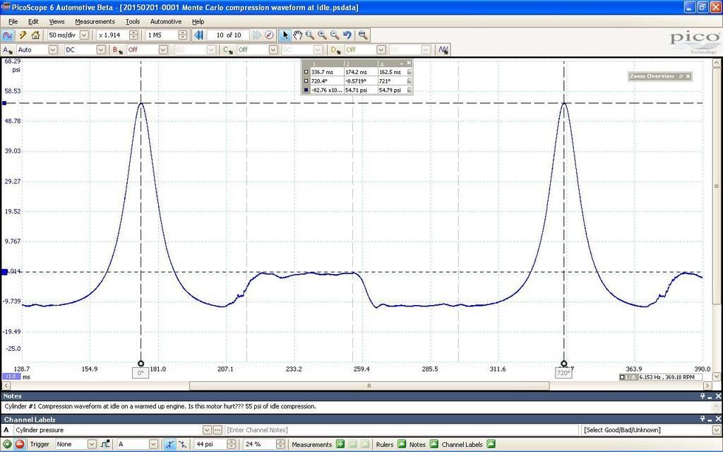
While not taken for this purpose, here is a screenshot of my Pico measuring the compression waveform of some stock 80's V6 car (note the seriously low compression!). The peak cylinder pressure points were marked as best as I could identify them while zooming in, and then the software splits that into the 720 degree engine cycle, and the four strokes. If I had a cam sensor waveform on a 2nd channel of the scope, and an injector control waveform, I could identify the number of degrees between the crank sensor signal and the injector EOIT. The problem is, and I don't know how Bluecat did this, how do we know which of the 24 crank sensor signals represents TDC compression on the cylinder we are later injecting fuel into?


 Reply With Quote

