The way I learned about turbos and tuning turbo engines was by examining the JDM variants,
Heres an sr20det for example, 2002 version
Attachment 118481
Here it is out of the car, an old version 1992 showing OEM PCV equipment on the side exposed so we can inspect it.
Attachment 118482
There is alot we can learn from these engines. The 98-02 model 2.0L engine from the factory will 300rwhp using OEM injectors/turbo.
The Silvia weighs 2800lbs so its basically a 12 second car from the factory that will survive for 250,000 miles or more (it will need an oil pump somewhere between 220k to 280k, or else) but I Digress, the point is examine the PCV system on them. Notice the valve cover AND oil pan are connected together to ensure their pressure signals always match and will not clog. The later model uses a hose at the rear to achieve this but the earlier models tie them together in a more obvious way near the center. The front hose of the valve cover... follow it down and see that it attached to the air filter tract, between filter and compressor cover. This ensures during WOT The crankcase (valve cover + oil pan) will be pulled down to the pressure of the intake tract, which is 0.5" Hg to 1.5"Hg for stock setups usually, using OEM air filters with up to 30,000 miles on the filter. This in turn will drive crankcase pressure down near or below atmospheric pressure, which is the ultimate GOAL of the pcv system for all operating conditions of the engine.
Crankcase pressure must never rise much above atmospheric pressure. Ideally it will be in the range of 0.5"Hg to 1.5"Hg. However I like to see 2.5"Hg to 3"Hg for additional cleaning and oil leak prevention. In other words, for stock setups 1.5"Hg is fine but if you are a performance setup you will drive more boost/power and make more blow-by therefore additional cleaning is warranted so just like anything else in performance world , improve it(You raised the boost, you raised fuel flow, you raised injector size, etc... we must also raise crankcase vacuum. It is just like any other setting you adjust).
Crankcase pressure diagnostics is not well known on forums for some reason, but the good mechanics always have a keen sense for it, I think.
here is an example from someone online, I forgot where but its a good extra reference point of view from somebody else kinda talking about the same issue from a different perspective.
crankcase-Pressure-testing.png
If you are new or feel unsure about how to measure or understand the crankcase pressure signal, Here is a easy way to introduce it,
The pressure measured inside the intake manifold is measured the same exact way we measure crankcase pressure.
That is, you may use a 2-bar map sensor to measure intake pressure/vacuum. And we may use a 2-bar map sensor to measure crankcase pressure.
here is an example of my setup to measure crankcase pressure using $12 Arduino microcontroller and a cheapy ebay $12 2-bar map sensor
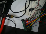 P1330906.jpg
Again just think of it as another intake manifold pressure signal. You measure it... then adjust it using orfices/venturi effects/air filter pressure drop/volume adjustments/baffle designs/aftermarket solutions (vacuum pump, electric or mechanical. Or exhaust driven)
In a way its the simplest of things. PCV is supposed to be simple and easy. But I think its so simple people dismiss it quickly without realizing how important it is. If something is so simple it can't be that important, right? And yet... PCV is probably the most important thing on an engine of all. It interfaces with and is the major component of control with respect to oil leaks, oil quality, piston ring function & sealing. Basically the long term health of an engine and it's ability to hold oil inside. I wouldn't waste my time doing all of this if I wasn't absolutely sure you need it.


 Reply With Quote